


Introduction
15
The channel’s circuit board with this harmonic analysis DSP is internally named the
"Amplitude DSP".
Frequency Measurement
Each scaled input passes to a second sub-system for additional analysis. This second
sub-system is internally named the “Supervisor DSP” board and consists of the
following portions:
Filter and High Speed ADC
—
Each input passes through an analog 1mHz low
pass filter, and sampled at 2mHz by a pair of 8-bit analog-to-digital converters.
Supervisory Processor—
The outputs of the pair of 8-bit converters is read by a
Motorola DSP56001, which performs several asynchronous tasks using this data.
This processor is linked to the central processor using the high speed RS485 data
link.
Range/Mode Control
Overload and Underload Detection
—
Each sample is checked for overload
status. If an overload is detected then the DSP changes the range presented to the
input scaling circuitry (if able) and informs the central processor that a range change
has occurred.
If an underload condition remains for longer than a period provided by the central
processor (actually set by the minimum fundamental frequency expected) then the
DSP changes the range presented to the input scaling circuitry (if able), and informs
the central processor that a range change has occurred. This process is continuous,
independent between the inputs, and completely independent of any other activities
in progress in the instrument. You can also set a fixed range, rather than the above
autorange process.
Bandpass Filtering and Frequency Measurement—
Input samples are
passed through a proprietary system. The system performs a tracking bandpass filter
function, maintaining track of the fundamental frequency reading within set range.
This tracked frequency reading is then used to measure the frequency of the
remaining signal component. This process is continuous and independent between
the inputs, and completely independent of any other instrument or supervisory
processor activities in progress.
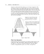
Sample Clock Generation
Under the direction of the central processor, the supervisory DSP controls circuitry
contained in an ASIC, which generates a digital clock signal whose average
Summary of Contents for Xitron 6000-2
Page 1: ...USER S GUIDE 6000 2 6000 3 Phase Angle Voltmeters...
Page 2: ......
Page 36: ...36 6000 2 3 User Guide Rev E...
Page 86: ...86 6000 2 3 User Guide Rev E...
Page 94: ...94 6000 2 3 User Guide Rev E...
Page 101: ...Appendix B 101...


