Vitek VTC-TNT30R3F Quick Start Manual Download Page 4

4

5

Installation

Before start, please make sure that the wall or ceiling is strong enough 

to withstand 3 times the weight of the camera. The mounting steps are 

as follows:

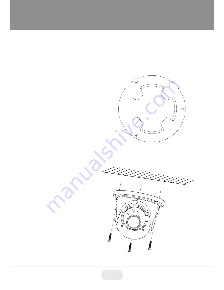
1. Attach the drill template to 

the place where you want to 

install the camera, then drill 

3 screw holes and 1 cable 

hole (if you want to route the 

cables through the mounting 

base) according to the drill 

template

.

2. Route the cables and 

connect the power & video 

cables, then secure the 

mounting base to the ceiling 

or wall with screws.

3. Loosen the lock screws, then  

adjust the camera to obtain 

the optimium viewing angle. 

Confirm the correct viewing 

angle with a monitor. (See 

next page for location of lock 

screws)

Focu

s

Zo

om

Summary of Contents for VTC-TNT30R3F

Page 1: ...True Mechanical Day Night function by ICR 3D DNR Noise Reduction On Board Motion Detection H 264 MJPEG Dual Streaming Onvif Compliance Remote Viewing via CMS Web Browser and iOS Android Apps Minimal...

Page 2: ...anual CD Waterproof Cap Foc us Zoo m This camera series supports both fixed and varifocal lenses Please note that the zoom and focus features mentioned below are not features of the fixed lens version...

Page 3: ...hernet patch cable then connect the cameras ethernet adaptor If not powering the camera with PoE also connect the power Cable to an approved 12VDC Power Supply 12VDC Optional 12VDC Power Connection No...

Page 4: ...era then drill 3 screw holes and 1 cable hole if you want to route the cables through the mounting base according to the drill template 2 Route the cables and connect the power video cables then secur...

Page 5: ...justments 5 Adjust the Focus and Zoom screws to achieve a clear image if your camera has a fixed lens please skip this step 6 Carefully remove the protective film from the lens to complete the install...

Page 6: ...all on the PC Open the installed application 3 Modify the IP address The default IP address is 192 168 226 201 Click the information of the camera listed in the above table to show the network informa...

Page 7: ...are as shown below IP address 192 168 226 201 HTTP 80 Subnet Mask 255 255 255 0 Data Port 9008 Gateway 192 168 226 1 You may use the above default settings when you log in the camera for the first tim...

Page 8: ...the camera by the router or virtual server for example 1 Make sure the camera is connected to the LAN Then log into the camera via LAN and go to System Congfig Network Config Port menu to set up the...

Reviews: