


TMC 3
September 2017
Visual Engineering
Video solutions. Integrated
visualengineering.co.uk
Page 6
Connections
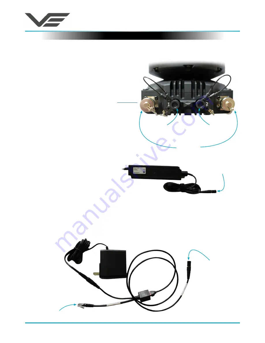
The TMC 3 has two TNC antenna and two Fischer
cable connections, as shown on the right.
Remove the protective caps from all connectors.
Connect the provided antennas to the TNC
connectors at the required orientation. Information
on antenna orientation is described in the
Mounting
section of this user guide.
Connect the GPS Module (110-3510) to
Plug 2
.
Antenna
Connectors
Power & Network
(
See Below)
GPS Module
Outdoor Deployment
The IP67 power supply connects directly
to
Plug 1
of the TMC 3 camera. All network
connections can be made through the
Mesh network.
The AC/DC power supply is connected to the Passive Power Injector cable (110-8301) which in turn
connects to the Fischer CAT5 Cable (110-3507), as shown below. Network connections can now be
made using a cable connection once the RJ45 plug of the injector cable is connected to the local
Ethernet network.
CAT5 Cable
110-3507
Connects to
network
AC/DC Power Supply
110-8910
Bench Use
Passive Power Injector
cable
110-8301
Connects to
Plug 1
Connects to
Plug 1


