background image

StreetView

June 2016

Visual Engineering

Video solutions. Integrated

visualengineering.co.uk

Page 9

PTZ  Camera Connections

It is necessary to connect power into the 

PTZ camera. 

These contacts have been left as bare 

ended wires to connect the camera directly  

to an AC power supply. 

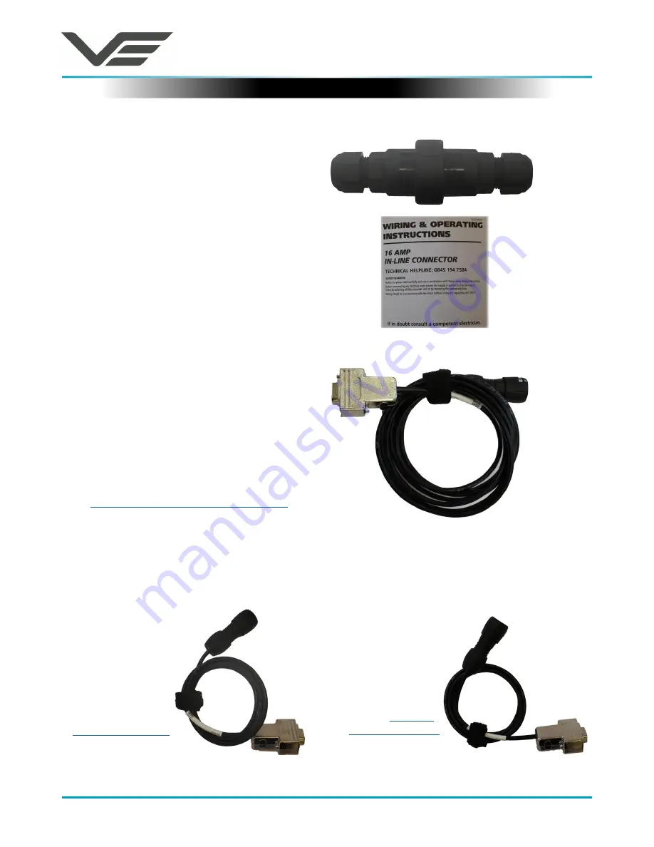
An IP68 rated in-line interface plug is 

included in the kit. Connecting the power 

into the PTZ camera should only be only 

carried out by a competent electrician.

Configuration Cables

In-line Power Connector

Camera COFDM Configuration Cable

110-8897

If the COFDM transmitter requires 

configuration connect the 8 pin binder 

connector cable shown here to the PTZ 

camera. Connect the other end, the D-Type 

connector, to a controlling PC and start 

the 

Video Transmission Control Software


application.

Camera Telemetry Configuration Cable

110-8898

If the telemetry radio requires  configuration 

connect the 8 pin 

binder connector 

cable shown here 

to the PTZ camera. 

Connect the other 

end, the D-Type 

connector, to a 

controlling PC 

and start the 

Telemetry Control


application.

Camera Control Cable

110-8899

For direct connection of the camera 

control connect the 8 

pin binder connector 

cable shown here 

to the PTZ camera. 

Connect the other 

end, the D-Type 

connector, to a 

controlling PC and 

start the 

Camera 

Control Software


application.

Summary of Contents for StreetView

Page 1: ...StreetView June 2016 Visual Engineering Video solutions Integrated visualengineering co uk Page 1 StreetView Digital Wireless CCTV System Pan Tilt and Zoom COFDM Wireless CCTV Video System...

Page 2: ...ontents 6 Key Components 7 Connecting the Antennas 8 PTZ Camera Antenna Connections 8 COFDM Video Receiver Antenna Connections 8 PTZ Camera Connections 9 In line Power Connector 9 Configuration Cables...

Page 3: ...une 2016 Visual Engineering Video solutions Integrated visualengineering co uk Page 3 Change History Version Date Change Summary Author v1 0 6 6 2016 Initial Draft RE v1 1 10 6 2016 Software Control A...

Page 4: ...step by step approach describing the simple initialisation sequence to get the user up and running in the shortest possible time Warranty and Support All Visual Engineering products are supplied as s...

Page 5: ...or wall or pole mounting The camera is powered from an AC mains supply At the receive end is a COFDM video receiver this is a stand alone IP66 rated rugged unit which receives video via two diversity...

Page 6: ...gether with their part numbers PTZ camera with video transmitter telemetry 10245 COFDM Video Receiver 110 8691 COFDM Antennas x 3 110 8852 PTZ Telemetry Antenna 110 8866 Video Receiver Telemetry Anten...

Page 7: ...le components of the PTZ camera video transmitter and the video receiver there are three COFDM antennas these are interchangeable between the PTZ camera and the COFDM video receiver There are also two...

Page 8: ...to the N Type connector labelled COFDM It is also necessary to connect the black telemetry antenna to the N Type port labelled TELEM The antenna connections should look like the image shown here COFDM...

Page 9: ...er requires configuration connect the 8 pin binder connector cable shown here to the PTZ camera Connect the other end the D Type connector to a controlling PC and start the Video Transmission Control...

Page 10: ...er and telemetry data connections Video Out Connector Control Telemetry Connections Video Diversity Antennas Telemetry Antenna Control Power and Telemetry Connector The 8 pin binder connection interfa...

Page 11: ...Software application on a PC The image here shows what the software application looks like To connect the software to the StreetView PTZ camera first connect the Camera Control Cable part number 110 8...

Page 12: ...l Software The StreetView transmitter and receiver radio system is built around Cobham COFDM technology To re configure the COFDM radio in either the PTZ camera or the Video Receiver connect the relev...

Page 13: ...off follow these steps Now power the unit on the following two characters will be displayed Within 2 seconds type the two letters ve The boot menu will be displayed as shown in the above screen grab e...

Page 14: ...ca 2 Pelco D 3 Pelco P 4 Main Menu 5 Exit Option 2 Unit Mode Select this to change type of unit 1 Camera 2 Controller 3 Repeater 4 Main Menu 5 Exit Option 3 Unit Address Select this to change address...

Page 15: ...powered off follow these steps Now power the camera on the following two characters will be displayed Within 2 seconds type the two letters ve The boot menu will be displayed as shown in the above scr...

Page 16: ...6 Panasonic 7 Main Menu 8 Exit Option 1 4 Unit Address Select this to change address of the PTZ camera 1 7 Address 1 to 7 Option 2 Motor Options Select this to change the motor parameters of the PTZ c...

Page 17: ...h 2 Medium 3 Low 4 Main Menu 5 Exit Option 3 Video Options Select this to change the video output mode of the PTZ camera 1 PAL 2 NTSC 3 720p 25 4 720p 29 97 5 720p 50 6 720p 59 94 7 1080i 50 8 1080i 5...

Page 18: ...slow shutter mode Telemetry Frequency 868MHz Camera Resolution 550TVL User Channels 16 Camera Power 240v AC Encryption AES128 AES256 Receiver Power 6 to 16v DC Connections Supplied Cables Camera Envi...

Page 19: ...tor Interfaces 110 8853 COFDM Video Receiver Cable Pin out 8 Pin Binder 9 Pin D Types 1 V 2 GND 3 Telemetry Data TX 2 Data RX 4 Telemetry Data RX 3 Data TX 5 GND 5 GND 6 Radio Module Cntrl TX 2 Cntrl...

Reviews: