MFR
August 2020
Visual Engineering
Video solutions. Integrated
visualengineering.co.uk
Page 8
Configuring the Camera
The MFR can be configured for a specific user profile, to include; communication settings, motor
control, video format and camera type. Once configured the camera will retain the settings.
The camera is configured using a menu structure on its control interface which is only accessible
at power on. To access the control menu it is necessary to connect the camera to a serial comms
software application, such as TeraTerm set to 9600 baud 8n1.
• Connect the power comms cable to a USB
port on a PC.
• Open the PC serial comms application
• Power on the camera, a > character will
appear and shortly after a ! character.
• As soon as the ! appears type v e in quick
succession.
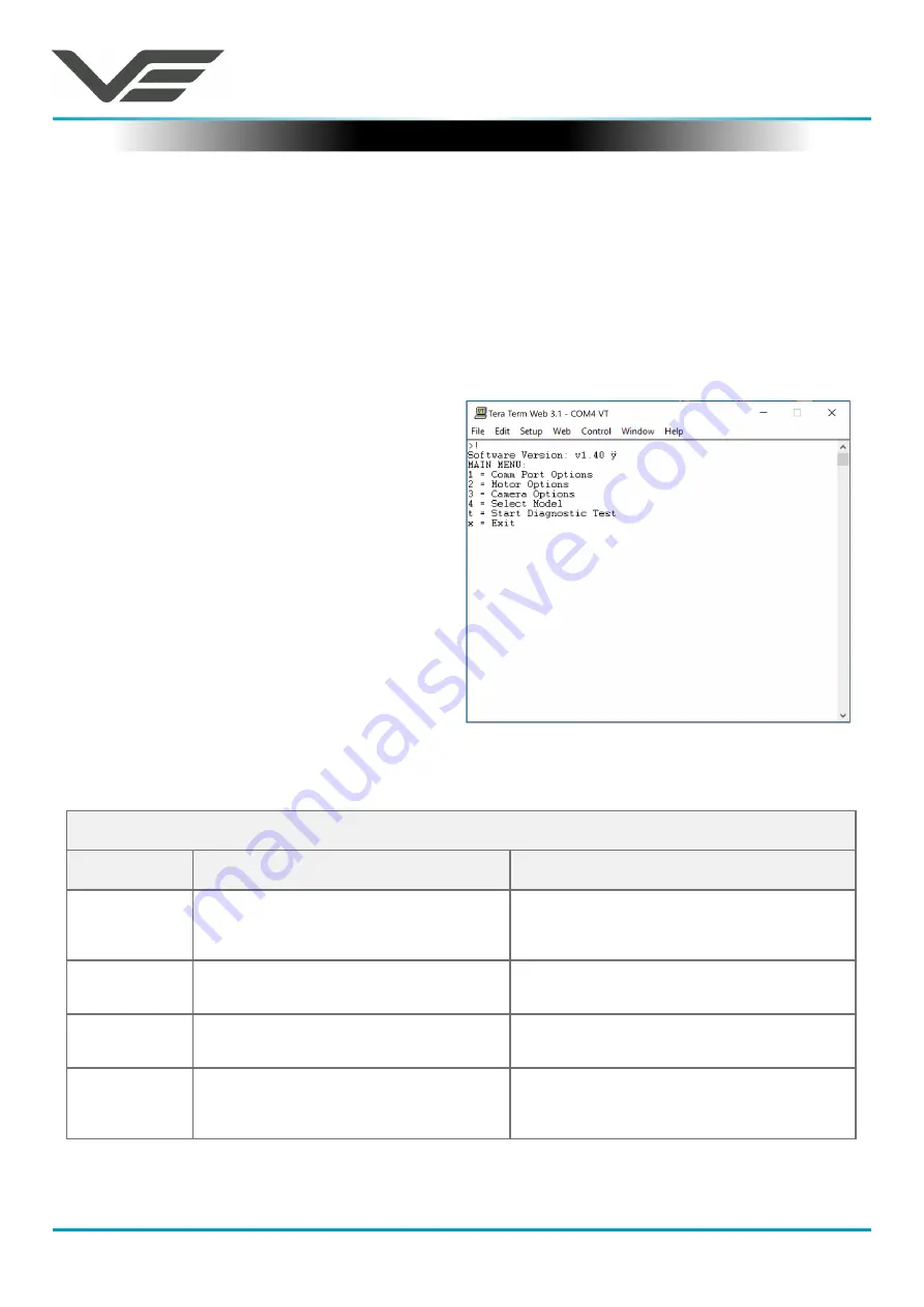
• The Main Menu shown on the right will then
be displayed.
• Select the required option.
• The function options are described in the
following tables.
Boot Menu
Comm Port Options
Comm Port Options
Sub Menu
Description
Options
Mode
The serial comms standard
RS485, No Parity , RS232, No Parity,
RS485, Odd Parity, RS232, Odd Parity
RS485, Even Parity, RS232, Even Parity
Baud Rate
The serial comms baud rate
1200, 2400, 4800, 9600, 19200,
38400, 57600, 115200
Protocol
The PTZ control protocol
Auto Detect, Visca, PelcoP,
PelcoD, Forward Vision
Unit Address
The camera’s unit address, this allows
several cameras to be connected on the
same comms bus.
1, 2, 3, 4, 5, 6, 7


