background image

MKIV

July 2016

Visual Engineering

Video solutions. Integrated

visualengineering.co.uk

Page 7

Configuring the Camera

The MKIV can be configured for a specific user profile, to include; video output format, 

communications format & camera control protocol. Once configured the camera will remember 

these settings.

The camera is configured using a menu structure on its control interface which is only accessible 

at power on. To access the control menu it is necessary to connect the camera to a serial comms 

software application, such as TeraTerm.

•  Connect the D-Type connector on the 

control cable to a Comm port on a PC.

•  Open the terminal application and 

configure the Comm port to 9600 baud

•  Re-power the camera, a > will appear and 

shortly after !

•  As soon as the ! appears type ‘v’ ‘e’ in quick 

succession.

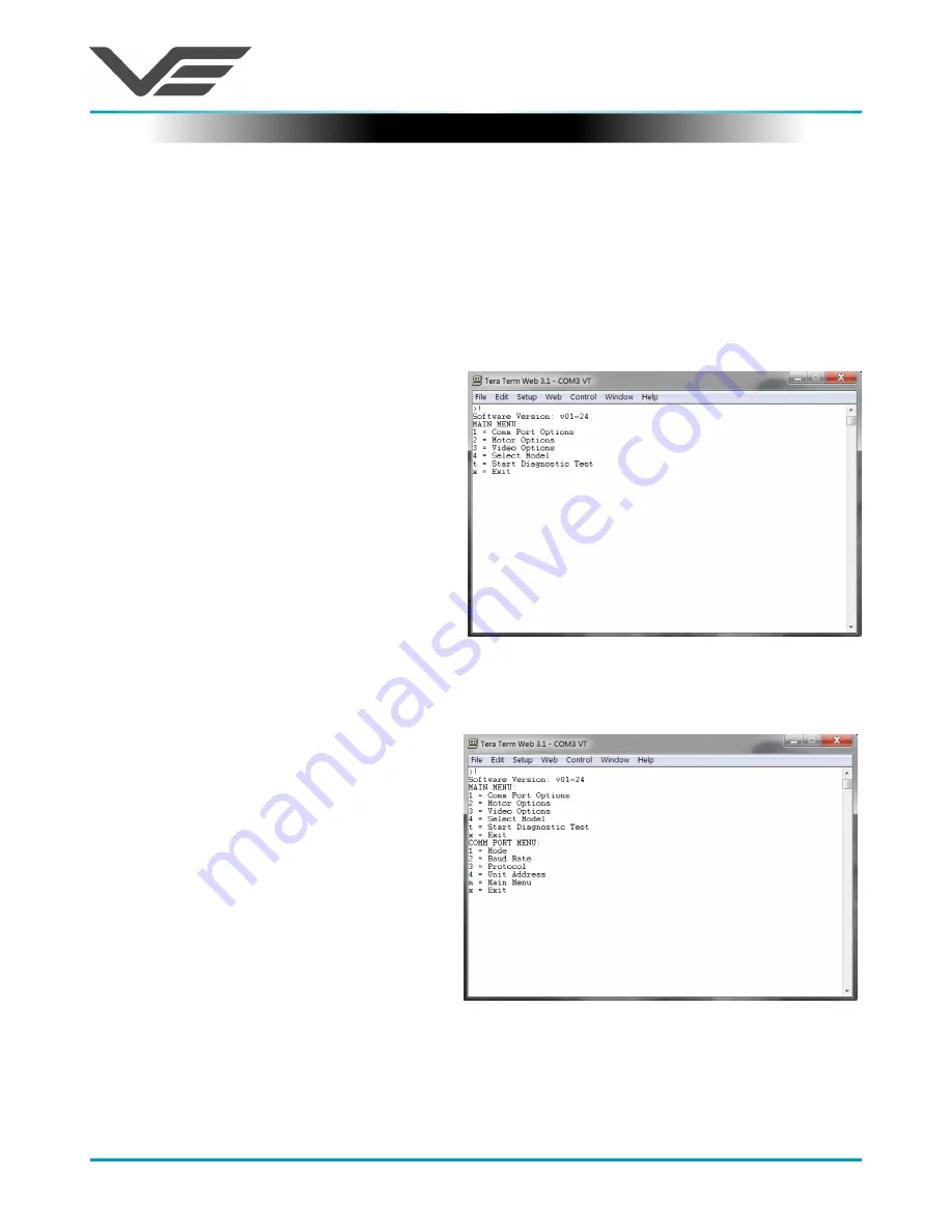
•  The Main Menu shown on the right will then 

be displayed.

The MKIV supports a range of control 

protocols such as Sony Visca & Panasonic.

•  From the Main Menu type 1 for the 

Comm Port Options. The menu shown on 

the right is displayed.

Setting the Control Protocol

Summary of Contents for 110-8926

Page 1: ...MKIV July 2016 Visual Engineering Video solutions Integrated visualengineering co uk Page 1 MKIV User Manual User Guide for the SD and HD Variants of the MKIV PTZ Camera ...

Page 2: ...able of Contents 2 Change History 3 About the User Manual 4 Warranty and Support 4 Kit Contents 5 Connecting the Camera 6 Configuring the Camera 7 Setting the Control Protocol 7 Setting the Video Output Format 8 Software Control 9 Connections 11 Specifications 11 Dimensions 12 Table of Contents ...

Page 3: ...MKIV July 2016 Visual Engineering Video solutions Integrated visualengineering co uk Page 3 Change History Version Date Change Summary Author v1 0 4 7 2016 Initial draft based on quick start guide RE ...

Page 4: ...to control the camera are explained The guide follows a step by step approach describing the simple initialisation sequence to get the user up and running in the shortest possible time This is followed up with a description of technical specifications connector interfaces and dimensions Warranty and Support All Visual Engineering products are supplied as standard with a 12 month Return to Base war...

Page 5: ...so contains the interconnect cable and a mains power supply with a range of wall connectors The kit contents are listed below along with their part numbers MKIV H HD PTZ Camera 110 8976 MKIV D SD PTZ Camera 110 8926 Cable Assembly 12 Way Power Comms Cable 110 8978 Power Supply AC DC 15V 1 6A 110 8661 USB Memory Stick Includes User Guide and Control Application 110 8679 ...

Page 6: ... for comms and DC power input RCA jack for composite video out To start using the MKIV follow these steps 1 Plug the mains power supply into a wall socket 2 Insert the Power Comms cable into the 12 pin binder connector on the base of the camera as shown in the image on the right Ensure the connector lugs are aligned before pressing it home gently 3 HD Variant Connect the HD SDI video out BNC conne...

Page 7: ...ccess the control menu it is necessary to connect the camera to a serial comms software application such as TeraTerm Connect the D Type connector on the control cable to a Comm port on a PC Open the terminal application and configure the Comm port to 9600 baud Re power the camera a will appear and shortly after As soon as the appears type v e in quick succession The Main Menu shown on the right wi...

Page 8: ... Menu type 1 Output Mode From the Output Mode Menu select whichever mode is required Following changes made using the control interface exit the boot menu by typing x the camera will now continue with its normal operation with the changes that were made Now type 3 for the Protocol options The current protocol is displayed in brackets On the example menu shown here option 02 Visca is currently acti...

Page 9: ...y Visca Panasonic protocols The user may choose to use a software controller of their choice or use the VE Camera Controller This software application is included on the USB memory stick in the kit It can also be downloaded from the Visual Engineering website www visualengineering co uk support The user should install the Software application on a PC The image below shows what the software applica...

Page 10: ...ng system has been made the user can go ahead and connect the application to the COM port In the example below the port COM3 has been selected Now select Connect Now that the software application is connected to the comms lead the functions of the software can be used In the example below the pan right command has been selected This will cause the MKIV camera to pan right Similar commands for pan ...

Page 11: ... Casing CNC Machined Delrin Connector Information Mating half Binder 720 female 12 pin P N 99 9134 02 12 Connections 12 Pin Binder Connector Pinout Pin Signal 1 12v DC 2 Power GND 3 CVBS 4 Video GND 5 Reserved 6 5v DC 7 RS232 TXD 8 RS232 RXD 9 Reserved 10 Reserved 11 Reserved 12 Reserved D Type Pinout Pin Signal 2 TX data from camera 3 RX data to camera 5 GND Both the MKIV H and MKIV D cameras hav...

Page 12: ...42 E sales visualengineering co uk Visual Engineering Technologies LLC 24928 Genesee Trail Road Suite 100 Golden CO 80401 USA T 303 526 0935 E sales visualengineering org MKIV July 2016 Visual Engineering Video solutions Integrated visualengineering co uk Page 12 ø 115 mm 177 4 mm Dimensions ...

Reviews: