


1 March, 2005
V1642OM.DOC
Page 3 of 9
2. INSTALLATION
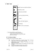
2.1 REAR
PANEL
CONNECTIONS
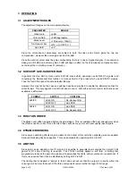
The rear module to be used with the V1642 is the same as that used with the V1645 Noise Reducer and
V1647 Aspect Ratio Converter. Some early units were delivered with rear modules that did not have a
D-type connector for GPI, in which case the Fade to Black input used two lower BNC connectors. Both
types of rear connector are shown below.
SD
(IN)
SD 1
(OUT)
SD 2
(OUT)
SD 3
(OUT)
RS
485
GP
I
SD
(IN)
SD 1
(OUT)
SD 2
(OUT)
SD 3
(OUT)
RS
485
5
6
SDI Input
SDI Loop O/P 1
SDI Loop O/P 2
SDI Loop O/P 3
Fade to Black
RS485 Remote Control
STANDARD 3U REAR
EARLY VERSIONS
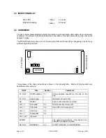
2.2 INTERFACING
SIGNAL
COMMENTS
Power
4.5W
Supplied from rack
SDI I/P
BNC
Video to SMPTE 259M
Max cable length >200m
SDI O/P 1, 2, 3
BNC
Video to SMPTE 259M. Drive cable length up to 200m
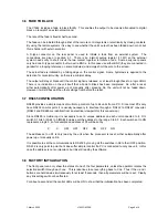
RS485
9 way D type
RS485 Remote Control. See below.
Fade to Black
9 way D type
GPI control of Fade to Black. See below.
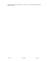
RS232
RS485
1
2
3
4
5
6
7
8
9
1
2
3
4
5
6
7
8
9
RX
TX
GND
TX B
RX A
TX A
RX B
GND
GPI
1
2
3
4
5
6
7
8
9
GND
FtoB
On the GPI connector some pins may carry other signals when used with compatible units. Therefore
only use pins 6 and 9 for the Fade to Black Function.