


2
D-303384 MC-302E PG2 Installation Instructions
WARNING!
To comply with FCC and IC RF exposure
compliance requirements, the magnet contact device should be
located in a distance of at least 20 cm from all persons during
normal operation. The antennas used for this product must not
be co-located or operated in conjunction with any other antenna
or transmitter.
1.
Insert a flat-edged screwdriver into
the slot and push upward to
remove cover.
2.
Remove screw
3.
Separate base from cover.
4.
Flex catch and remove P.C. board
5.
Mark & drill 2 holes in mounting
surface.
Fasten base with 2 countersunk
screws.
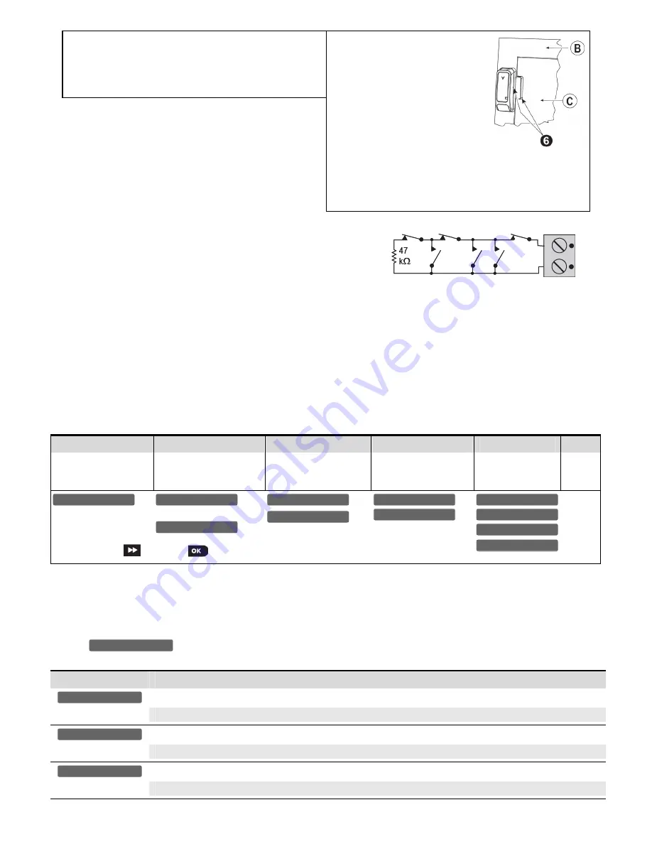
6.
Mount the magnet near its location
mark with 2 screws
A.
Enroll button
B.
Fixed frame
C.
Moving part
Figure 3b.
Mounting
2.2 Auxiliary Input Wiring
(Fig. 4)
A
. Connect the auxiliary sensor contacts across the MCT-302E auxiliary
input terminals.
B.
If the auxiliary input of the MCT-302E PG2 is defined as a Normally
Closed (N.C.) type, series connected N.C. sensor contacts must be
used exclusively. An E.O.L. resistor will not be required.
Figure 4.
E.O.L. Wiring Example
C.
If the auxiliary input of the MCT-302E PG2 is defined as a Normally Open (N.O.) type, parallel connected N.O. sensor contacts must
be used exclusively. An E.O.L. resistor will not be required.
D.
For E.O.L. supervision:
Normally Closed (N.C.) sensor contacts can be used, as shown in Figure 4. A 47k
E.O.L. resistor must be wired at the far end of the
zone loop.
Note:
For UL installations, the device connected to the initiating circuit must be located in the same room as the transmitter.
The drawing below illustrates a N.O. and N.C. alarm circuit with E.O.L. resistor.
Note:
An alarm message is transmitted once the loop is opened or short circuited.
2.2. Enrollment
Refer to the PowerMaster panel's Installer Guide and follow the procedure under the
"
02:ZONES/DEVICES
"
option of the Installer Menu.
A general description of the procedure is provided in the following flow chart.
Step 1
Step 2
Step 3
Step 4
Step 5
Step 6
Enter the Installer menu
and select
“
02:ZONES/DEVICES
”
Select "
ADD NEW
DEVICE
" Option
See Note [1]
Enroll the device or Enter
the device ID
Select the desired Zone
Number
Configure Location,
Zone Type &
Chime Parameters
Configure
the
Magnet
means scroll
and select
See Note
[2]
Notes:
[1] If the magnetic contact device is already enrolled you can configure the magnetic contact device parameters via the
“Modify Devices”
option
– see Step 2.
[2]
Select the
"Device Settings"
option and refer to section 2.3 to configure the magnetic contact device parameters
.
2.3. Configuring the Magnetic Contact Device Parameters
Enter the
menu and follow the configuration instructions for the MC-302E PG2 magnetic contact device as described in the
following table.
Option
Configuration Instructions
Determine whether or not the alarm LED indication will be activated.
Optional settings:
LED Enabled
or
LED Disabled
(default).
Determine whether to enable or disable the internal reed switch.
Optional settings:
Enabled
or
Disabled
(default).
Define the external input according to the installer's requirements.
Optional settings:
Disabled
,
EOL-End Of Line
(default),
Normally Open
or
Normally Closed
.
Input #1
Reed Switch #1
Alarm LED
DEVICE SETTINGS
Z06.DEV SETTINGS
Z06.SET CHIME
Z06.ZONE TYPE
Z06.LOCATION
ID No. 101-XXXX
Z06:Contact Sens
ENTR ID:XXX-XXXX
ENROLL NOW or
MODIFY DEVICES
ADD NEW DEVICES
02.ZONES/DEVICES


