www.visonic.com
Page 6 of 11
D-306783 ioXpander-12x4 Module (Rev 2, 11/17)
5.
Connecting the ioXpander-12x4 Module
5.1
Wiring:
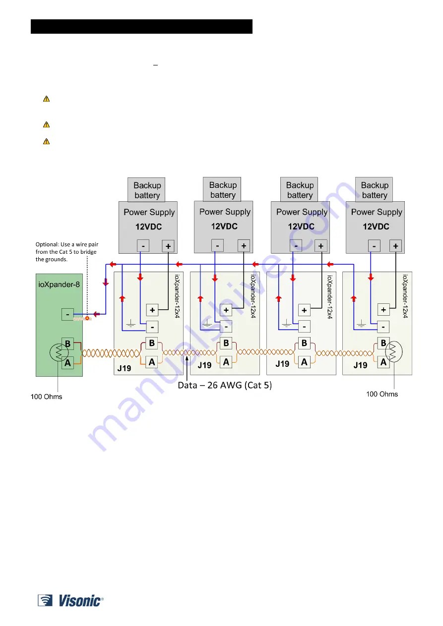
Power should be wired using < 22 AWG. Data should be wired using 26 AWG (Cat 5).
The wired detector should be installed
at least 2 meters
away from the control panel.
The Panel that connects to the ioXpander-12x4 Module should be wired as a bus configuration.
Use only a power supply that is safety approved for IEC/EN 60950-1 as a limited power source (LPS) with a
rated voltage of 12Vdc and rated current of __1__a max.
Both the CP and PS that are used for powering the ioXpander-12x4 Module must be EN 50131-6 certified.
The loads that can connect to the relay outputs must be limited to a maximum of 12 VDC, 8A or 24 VDC, 4A!
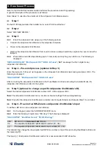
Example of ioXpander-12x4 Modules connected to external power supply with 12 hour backup battery.
5.2
Termination:
Each end of the RS-485 bus must be terminated with a 100 Ohm resistor.


