background image

1

. Descriptions of Main Unit and Remote-Control Unit

.

1

1

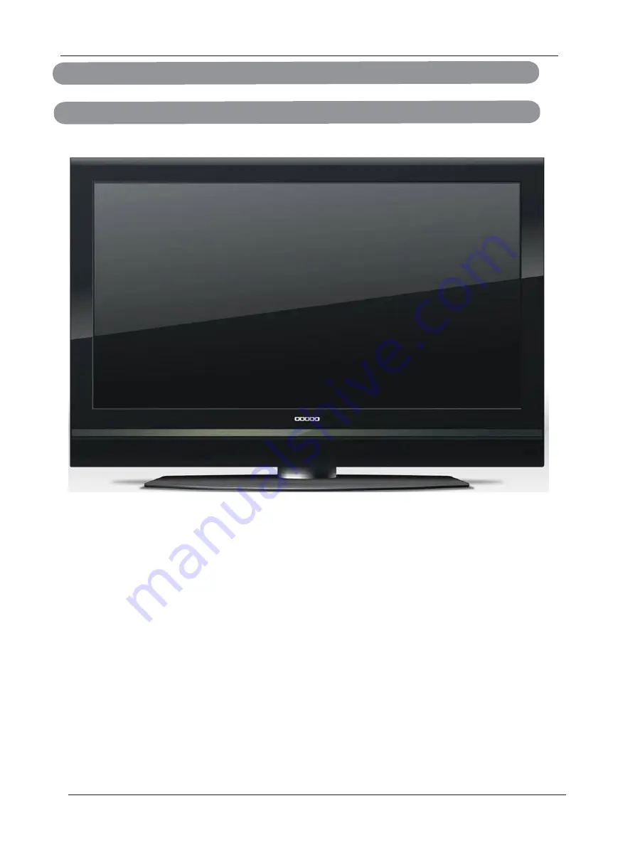
.1 Front Panel Control 

1

.1.1. POWER: Press to turn on and off the TV.   


1

.1.2. INPUT: Press to show the input source mode. 

1

.1.3. Menu :Menu display. 

1

.1.4. CH+/-: Press to scan thought channels. 

1

.1.5. VOL +/-: Press to turn up/down the volume 

14

6

Summary of Contents for LVQ-37HLR-FHD

Page 1: ...es not accommodate the three wire plug have an electrician install the correct outlet or use an adapter to ground the appliance safely Do not defeat the safety purpose of the grounded plug Do not over...

Page 2: ...the mast and supporting structure grounding of the lead in wire to an antenna discharge unit size of the grounding conductors location of antenna discharge unit connection to grounding electrodes and...

Page 3: ...ase handle the product gently Never place the unit on a surface with the glass facing downwards unless it is on protective padding When opening the carton check that the product is in good condition a...

Page 4: ...Please ensure the product is installed with the screen in landscape orientation Any 90 clockwise orcounterclockwise installation may induce poor ventilation and excessive component damage Preparing Y...

Page 5: ...t 7 1 3 Illustration of the Interface Panel 9 4 Specifications 19 2 Connection and Preparation 10 2 1 Connect Antenna or Video Facility 10 2 2 Battery Installation of Remote Control Unit 10 2 3 Auto S...

Page 6: ...Control Unit 1 1 1 Front Panel Control 1 1 1 POWER Press to turn on and off the TV 1 1 2 INPUT Press to show the input source mode 1 1 3 Menu Menu display 1 1 4 CH Press to scan thought channels 1 1 5...

Page 7: ...1 2 Remote Control Unit 7...

Page 8: ...nu Press this button to enter the menu screens for various optional adjust able settings INPUT Press this button to switch among TV broadcast AV input program and other source PMODE Press this button...

Page 9: ...Audio In 12 3 YPBPR2 Right Audio in 13 4 YPBPR2 LEFT Audio In 14 5 CVBS S VIDEO Right Audio In 15 6 CVBS S VIDEO Left Audio In 16 7 YPBPR2 Y 17 8 18 9 19 10 20 9 YPBPR1 Y YPBPR2 PB YPBPR1 PB YPBPR2 PR...

Page 10: ...de down Scratch the grip of the battery compartment 2 Install two new 1 5V AAA batteries make sure the anode and cathode of the batteries matches the marks inside the battery compartment Or not it wou...

Page 11: ...on on the green signal This is most commonly used for PC input better analog Analog HD1 HD2 Component The video signal is separated into three signals one containing the black and white information an...

Page 12: ...should be connected to the HDMI input of the HDTV for optimal results Connecting DVD Player Best 1 Turn off the power to the LCD TV and DVD player 2 Connect a HDMI cable to the HDMI output of your DV...

Page 13: ...ble white and red connectors connect cable to the audio output connecters associated with the DVI out put on the rear of your DVD Player and connect the other end to the audio connectors white area as...

Page 14: ...t Analog HD1 group green color band in the rear of your LCD TV 5 Connect the R red color and L white color audio connectors on the rear of your DVD player to the R red color and L white color audio in...

Page 15: ...d L white color audio connectors on the rear of your DVD player to the R red color and L white color audio input connectors in the side of your LCD TV 4 Turn on the power to the LCD TV and DVD player...

Page 16: ...our Antennaor Digital cable for DTV 1 Turn off the power to your LCD TV 2 Connect the coaxial RF connector from your Antenna or Digital Cable to the DTV connector on the rear of your LCD TV 3 Turn on...

Page 17: ...he rear of your LCD TV 3 Turn on the power to your LCD TV 4 Select TV using the INPUT button on the front of your LCD TV or directly by pressing the NTSC TV button on the Remote Control 3 4 3 Using th...

Page 18: ...button on the front of your LCD TV or directly by pressing the RGB button on the Remote Control Note a For the best picture quality when connecting a computer through Rgb set your computer timing mode...

Page 19: ...n packed 1025x370x780mm Accessories Remote Control Power cord Attention cord Registration card User Guide Power requirement AC 100 240V 50 60Hz Normal Power Dissipation 250W The whole machine paramete...

Page 20: ...SD On Screen Display function enables you to adjust the screen status conveniently since it provides graphical presentation Choosing a TV channel 1 Press CH CH button on the front panel or on the remo...

Page 21: ...er Wide Audio Setup Feature Audio Mode Audio Language Bass 50 Treble 50 Balance 0 Digital Audio Output Voice Picture English PCM Audio Setup Feature Tuning Band Signal Level Auto Ch Search Add On Ch S...

Page 22: ...e picture Aspect Ratio Press button to select this item then press ENTER button to adjust the aspect the aspect ratio of the picture Available aspect ratio FullScreen Normal Zoom Wide Cinema Waterglas...

Page 23: ...e Picture Mode to User first if you want to change the value of Bass Treble TIPS you can select the picture mode directly by pressing SMODE button repeatedly User Voice Concert Jazz Press button to se...

Page 24: ...nnel selected press button to select the position of letter press button to set the name Channel Labels Menu To Exit Exit Ch 42 1 ATSC dmo Analog Channels Found Auto Ch Search Air Performing First Pas...

Page 25: ...repeatedly as 15mins 30mins 45mins Advanced Video Menu Press button to select this item then press ENTER button for Advanced Video Menu Advanced Video Menu Noise Reduction Medium Normal On Press MENU...

Page 26: ...and after set the new password you need to enter it again to confirm it Master Lock Press ENTER button to set the Master Lock on off if you set this function on all the parental control lock will be u...

Page 27: ...SAMPLE To Move To Exit Exit To Select Enter US Ratings Menu MPAA TV Rating NONE G PG PG 13 R NC 17 X Canadian Rating Menu Canadian English Candlan French E C C8 G PG 14 18 E G 8 ans 13 ans 16 ans 18 a...

Page 28: ...et Menu Sleep Timer Advanced Video Menu Picture Off VGA Set VGA Set Press button to select VGA Set then press ENTER button for VGA Setting Men VGA Setting 1024x768 70Hz Auto Adjust Setting Prese t H P...

Page 29: ...s ENTER button to adjust the phase of the picture Clock This function is unavailable in component mode V Position Press ENTER button to adjust the vertical position of the picture H Position Press ENT...

Page 30: ...al Frequency K HZ Pixel Clock MHZ Standard mode 48 36 60 65 00 VESA Guidelines 56 48 70 75 00 VESA Standard 1024 x768 60 02 75 78 75 VESA Standard 63 981 60 80 45 VESA Guidelines 1280 x768 79 976 75 8...

Page 31: ...ck if the TV AV button is set to AV position Picture lacks color or picture too dark Check color brightness and contrast controls are correctly adjusted All channels lose color Intermittently Check if...

Reviews: