


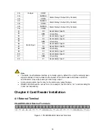


12
C18
Output
COM1
C19
NO/NC2
Alarm Relay 2 Output (Dry Contact)
C20
COM2
C21
NO/NC3
Alarm Relay 3 Output (Dry Contact)
C22
COM3
C23
NO/NC4
Alarm Relay 4 Output (Dry Contact)
C24
COM4
D1
Event Input
C8
Event Alarm Input 8
D2
GND
Grounding
D3
C7
Event Alarm Input 7
D4
C6
Event Alarm Input 6
D5
GND
Grounding
D6
C5
Event Alarm Input 5
D7
C4
Event Alarm Input 4
D8
GND
Grounding
D9
C3
Event Alarm Input3
D10
C2
Event Alarm Input 2
D11
GND
Grounding
D12
C1
Event Alarm Input 1
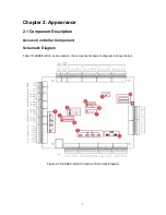
Note:
The Alarm input hardware interface is normally open by default. So only the normally open
signal is allowed. It can be linked to the buzzer of the card reader and access controller,
and the alarm relay output and open door relay output.
Arming region alarm input is only for the alarm relay output linkage.
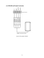
RS485 card ID should be set as 1to 8. For example, the ID of door 1 is 1 and 2 standing for
in and out respectively.
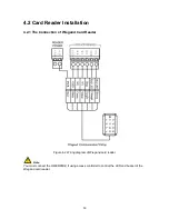
Chapter 4 Card Reader Installation
4.1 External Terminal
VS-AXESS-4DLX External Terminals
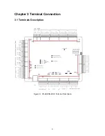
Figure 4-1 VS-AXESS-4DLX External Terminals


