background image

Table 2-1 Description of Rear View 


No.


Name


Cable Interface of RS-485, Power, LED Control, etc. 

Buzzer 

Tamper-proof Module 

DIP Switch 


2.3 Side View 

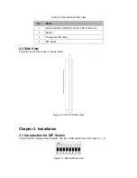
The side view of card reader is shown below: 


Figure 2-3 VIS-3103 Side View 


Chapter 3. Installation 

3.1 Introduction for DIP Switch


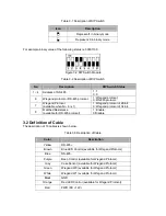
The DIP switch module is shown below. The No. of DIP switch from left to right is 1 ~ 8. 


Figure 3-1 DIP Switch Module 


Summary of Contents for VIS-3018

Page 1: ...Access Control Black with Clear Border Card Reader and Keypad Reader Only Compatible with Wiegand 26 and 34 Bit VIS 3103 Installation Manual...

Page 2: ...FOR ANY SPECIAL CONSEQUENTIAL INCIDENTAL OR INDIRECT DAMAGES INCLUDING AMONG OTHERS DAMAGES FOR LOSS OF BUSINESS PROFITS BUSINESS INTERRUPTION OR LOSS OF DATA OR DOCUMENTATION IN CONNECTION WITH THE U...

Page 3: ...oduct to your local supplier upon the purchase of equivalent new equipment or dispose of it at designated collection points For more information see www recyclethis info 2006 66 EC battery directive T...

Page 4: ...uivalent type only Dispose of used batteries according to the instructions provided by the manufacturer Preventive and Cautionary Tips To guarantee the card reader works properly please read and obey...

Page 5: ...IONARY TIPS CHAPTER 2 INTRODUCTION 2 1 FRONT VIEW 2 2 REAR VIEW 2 3 SIDE VIEW CHAPTER 3 INSTALLATION 3 1 INTRODUCTION FOR DIPSWITCH 3 2 DEFINITION OF CABLE 3 3 WIRING CABLES 3 4 INSTALLING CARD READER...

Page 6: ...gand protocol And a build in tamper proof module helps to protect card reader from malicious damage As to the physical appearance the PC ABS material makes water proof and dust proof possible in poor...

Page 7: ...uzzer 3 Tamper proof Module 4 DIP Switch 2 3 Side View The side view of card reader is shown below Figure 2 3 VIS 3103 Side View Chapter 3 Installation 3 1 Introduction for DIP Switch The DIP switch m...

Page 8: ...6 is 1 1 Wiegand protocol of 26 bit 0 Wiegand protocol of 34 bit 8 Matched Resistance available for RS 485 protocol 1 Enable 0 Disable 3 2 Definition of Cable The description of 10 cables is shown be...

Page 9: ...rd mode For details please refer to 3 2 Introduction for DIP Switch 3 Wire the cable between controller and card reader as shown below Figure 3 3 Wiring for RS 485 Communication Mode Steps for Wiegand...

Page 10: ...switch For details refer to 3 2 Introduction for DIP Switch Steps 1 Fix the plate on the wall or other place 2 Connect the cables between controller and card reader For details refer to 3 4 Wiring Ca...

Page 11: ...essing keys prompt Swiping card prompt Time out prompt for pressing keys or swiping card Wiegand protocol Pressing keys prompt Swiping card prompt Two rapid beeps The operation of pressing keys or swi...

Reviews: