Vision™ OPLC™ V290-19-C30B, V290-19-T40B
4
Unitronics
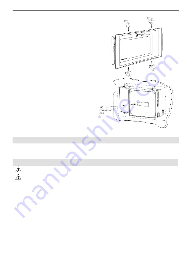
3. Slide the controller into the cut-out, ensuring
that the rubber seal is in place.
4. Push the 4 mounting brackets into their slots
on the sides of the controller as shown in the
figure to the right.
5. Tighten the bracket screws against the
panel. Hold the bracket securely against the
unit while tightening the screw.
6. When properly mounted, the controller is
squarely situated in the panel cut-out as
shown in the figure to the right.
I/O Modules
I/Os are integrated into the system via Snap-in Modules and I/O Expansion Modules. Installation
instructions and other data may be found in the module’s technical specification sheet.
Wiring: General
Do not touch live wires.
Unused pins should not be connected. Ignoring this directive may damage the device.
Caution
To avoid damaging the wire, do not exceed a maximum torque of 0.5 N·m
(5 kgf·cm).
Do not use tin, solder, or any substance on stripped wire that might cause the wire
strand to break.
Use crimp terminals for wiring; use 26-14 AWG wire (0.13 mm
2
–2.08 mm
2
).
1. Strip the wire to a length of 7±0.5mm (0.250–0.300”).
2. Unscrew the terminal to its widest position before inserting a wire.
3. Insert the wire completely into the terminal to ensure a proper connection.
4. Tighten enough to keep the wire from pulling free.


