

B.
Insert cable into slots using
cable balls to hold them in place.
Secondary Arm
Cable Cover
Primary Arm
Cable Cover
Primary Arm
Cable Cover
Secondary Arm
Cable Cover
F.
Route the Notebook Cables
through the Cable Management
Clip on the back of the Notebook
Tray.
A.
Route the Cables underneath the Arms, inserting the Primary
and Secondary Arm Cable Covers to hold the Cables in place.
TIP: Leave enough slack in the cables
at the joints to allow full movement.
D.
Insert the Top
Cap and Allen Key
into the Pole.
C.
Lock the Handgrip at
desired height.
T
F
I
L
First Handgrip
Tab
Arm
Assembly
Installation Complete
No portion of this document or any artwork contained herein should be reproduced in any way without the express written consent Atdec Pty Ltd.
Due to continuing product development, the manufacturer reserves the right to alter specifications without notice. Published 06.09.12 ©
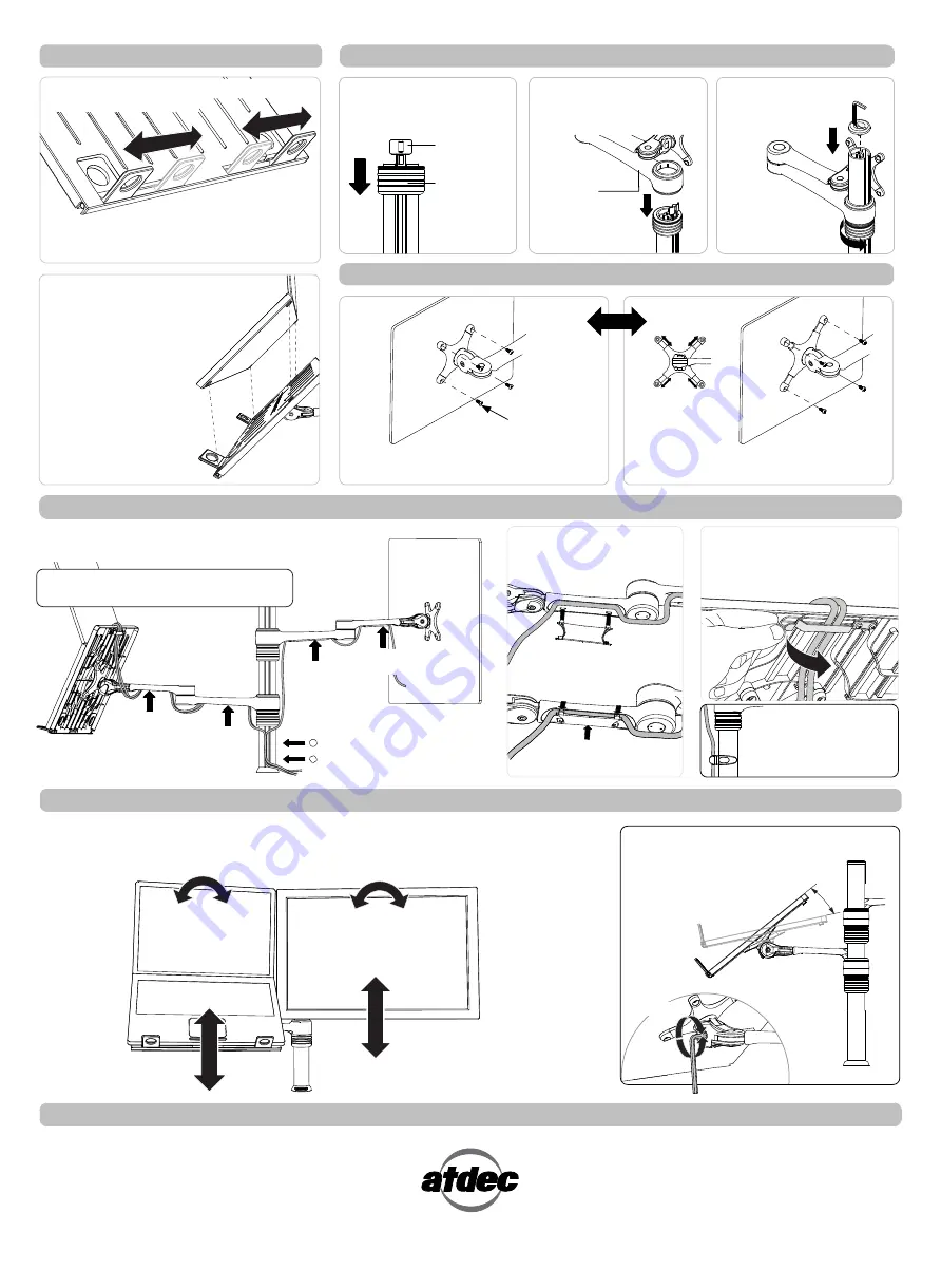
Step 4. Install the Notebook
NOTE:
Ensure that the Support Tabs do not
obstruct any cable ports.
B.
To increase stability, use the self
adhesive Hook-and-Loop Fasteners
supplied:
• Peel off the backing paper
from the fasteners.
• Attach fasteners to your
Notebook Computer and
the Notebook Tray.
• Ensure that each set of
fasteners are correctly
aligned,
i.e. Hook to Loop.
Step 6. Fasten Display to Monitor Arm
For displays with 75mm x 75mm
mounting hole patterns
For displays with 100mm x 100mm
mounting hole patterns
Step 8. Cable Management -
Ensure arms are fully extended before attaching cables.
M4 Display
Mounting Screws
tabs
Pull-out
Step 5. Attach the Monitor Arm to Pole Assembly
A.
Adjust the Support Tabs to suit the width of
your Notebook Computer.
NOTE:
If this product is in a
Multi-user environment, use
the supplied Cable Clip to
secure the cables to the pole.
C.
Insert tabs
D.
Push-in
E.
Then Push-up
A.
Insert First Handgrip back
onto the Pole so that the Tab
protrudes.
B.
Slip the Arm Assembly
over the Handgrip Tab and
then onto the Pole.
Step 9. Display Alignment
Set the height and position of the Notebook Tray and Monitor as desired.
The height can be adjusted by unlocking the Handgrips (see Steps 3, E and F).
For the optimal position of your display, refer to the Ergonomic Guidelines in your ‘User Operating Card’.
±5° Horizontal
Adjustment
95° Portrait/
Landscape Rotation
Adjust the tilt angle of the Notebook Tray
as desired, locking it in position using
the 5mm Allen Key supplied.
25° TILT
LOOSEN
TIGHTEN
To Insert Cable Covers
OR
Note: DO NOT
OVER TIGHTEN


