VT DSO-2A20 Manual Rev. 1.1
Virtins Technology
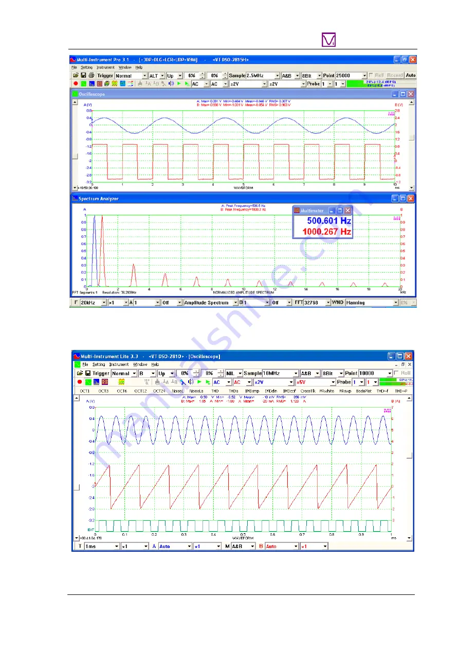
The following figure is a mixed signal display. Channels A & B are analog input channels while Channel EXT is used as a digital input channel.
www.virtins.com 46 Copyright © 2017 Virtins Technology
Page 1: ...is absolutely dangerous to connect an unknown external voltage to the VT DSO unit Be sure that the voltage to be measured is less than the maximum allowed input voltage Note VIRTINS TECHNOLOGY reserves the right to make modifications to this manual at any time without notice This manual may contain typographical errors www virtins com 1 Copyright 2017 Virtins Technology ...
Page 2: ...des 20 1 8 8 Signal Generator DDS Interpolation 21 1 8 9 Simultaneous Data Acquisition and Data Output 21 1 8 10 Calibration and Re Calibration 22 1 8 11 Upgradable software firmware and hardware based DSP algorithm 23 1 9 NON ROUTINE APPLICATIONS 23 1 9 1 Frequency Response Measurement 23 1 9 2 Distortion Noise Level and Crosstalk Measurements 26 1 9 3 Measurement of Derived Quantities 26 1 9 4 S...
Page 3: ... used in conjunction with Multi Instrument software the USB DSO converts any desktop laptop or tablet PC into a powerful oscilloscope spectrum analyzer multimeter data logger signal generator and so forth all of which work simultaneously 1 1 Package Contents A standard VT DSO 2A20 Package contains the following items 1 VT DSO unit with a hardware bundled Multi Instrument Standard software license ...
Page 4: ... port may not be enough for the DSO In this case a USB cable with two USB A type connectors at one end one is black and the other is red and one USB B Type connector at the other end can be used The black A type connector should be connected to a USB port of your computer while the B type connector should be connected to the DSO unit The red A type connector should be connected to another USB port...
Page 5: ...Select Install from a list or specific location Advanced and click Next 3 Choose Search for the best driver in these locations and Browse and then locate the driver The driver can be found at Multi Instrument s installation directory Drivers VTUSB3 32bit or 64bit Choose 32 bit or 64 driver according to your Windows version After that press Next www virtins com 5 Copyright 2017 Virtins Technology ...
Page 6: ...VT DSO 2A20 Manual Rev 1 1 Virtins Technology 4 The following dialog box will pop up Click Continue Anyway 5 Click Finish www virtins com 6 Copyright 2017 Virtins Technology ...
Page 7: ...O 2A20 Manual Rev 1 1 Virtins Technology 6 Select No not this time and click Next 7 Select Install from a list or specific location Advanced and click Next www virtins com 7 Copyright 2017 Virtins Technology ...
Page 8: ...then locate the driver The driver can be found at Multi Instrument s installation directory Drivers VTUSB3 32bit or 64bit Choose 32 bit or 64 driver according to your Windows version After that press Next 9 The following dialog box will pop up Click Continue Anyway www virtins com 8 Copyright 2017 Virtins Technology ...
Page 9: ...7 1 If there is an available internet connection Windows 8 will silently connect to the Windows Update website and search for the driver The following dialog box will pop up Click Close or let it close automatically after failing to find the driver www virtins com 9 Copyright 2017 Virtins Technology ...
Page 10: ...tart Screen via Charm Bar Settings Control Panel Hardware and Sound Device Manager In the Device Manager window there will be an Unknown device under Other Device with a yellow warning symbol to indicate that the driver for the device has not been installed Right click on the Unknown device and choose Update Driver Software on the pop up menu www virtins com 10 Copyright 2017 Virtins Technology ...
Page 11: ...his location and Browse and then locate the driver The driver can be found at Multi Instrument s installation directory Drivers VTUSB3 32bit or 64bit Choose 32 bit or 64 driver according to your Windows version After that press Next 5 Choose Install to start the driver installation www virtins com 11 Copyright 2017 Virtins Technology ...
Page 12: ...re installation stick to a fixed USB port of your computer for the VT DSO unit 1 3 2 Installation Verification If the hardware driver has already been installed the LED on the DSO s front panel will blink red once whenever you attach the DSO to the computer You can follow the steps in the next section to start the Multi Instrument software If the software starts in licensed mode do not plug out th...
Page 13: ...cilloscope is running the LED will be steady green If the signal generator is running it will be steady red If both are running it will be steady orange If some error occurs it will blink red at a slow speed 1 5 Zeroing Connect the oscilloscope probe tip to its ground lead for both channels and switch the Trigger Mode to Auto see the figure above With the oscilloscope running you should see a hori...
Page 14: ... Adjust the probe compensate capacitor at the end of the probe cable such that the square wave looks normal as shown below For VT DSOs such as VT DSO 2810R and VT DSO 2820R that do not have a built in analog signal generator the probe calibration signal is generated digitally and output via a dedicated pin For VT DSOs such as VT DSO 2810 and VT DSO 2820 that have a built in band limited 5MHz analo...
Page 15: ...of these features are not available in other USB DSOs in the market For a complete description of functions please refer to the Multi Instrument software manual 1 8 1 Hardware DSP based Bit Resolution Enhancement for Oscilloscope Hardware DSP based bit resolution enhancement is a unique feature that is only found in the second generation VT DSOs Virtins Technology is the first and currently the on...
Page 16: ...mpling rate is required for continuous recording under streaming mode The above bit resolution enhancement is realized through hardware It is also possible to implement this feature through software After the acquired data have been transferred from the DSO into the computer one can apply a moving average digital filter a FIR filter with equal filter coefficients to them A 2 tap moving average fil...
Page 17: ...d Length Low limited by DSO hardware buffer size High limited by hard disk space Medium limited by computer memory size Trigger Trigger per frame Trigger required at startup first frame only Trigger required at startup first segment only Discontinuity within each data frame Absolutely no Normally no Normally no Discontinuity between adjacent data frames Most likely Normally no Normally no Usage Ge...
Page 18: ...ure uninterrupted data recording Whether the recorded data are continuous i e the adjacent frames of data are connected smoothly without missing any data in between or not depends on the system throughput sampling frequency bit resolution number of sampling channels etc The DAQ progress bar under the oscilloscope graph shows the recording progress The progress bar will be filled with some red colo...
Page 19: ... 3 1 Digital Triggering The second generation VT DSOs use a digital trigger instead of the conventional analog trigger The digital trigger is implemented through hardware It is able to search for the trigger event in the digitized samples in real time Trigger jitter is a significant problem in conventional analog trigger It is caused by the disparity between the acquisition and trigger circuits Tr...
Page 20: ...ation VT DSOs solve this problem using anti aliasing filters that can adapt to the sampling frequency 16 bit resolution should be used to fully utilize this feature Please refer to the hardware specifications for details 1 8 7 Signal Generator DDS and Streaming Modes The signal generator of the second generation VT DSOs features advanced hardware based DSP algorithm which supports both streaming a...
Page 21: ... Instrument software manual for details 1 8 8 Signal Generator DDS Interpolation A DDS DAC device uses a lookup table i e DDS buffer to hold the shape of the signal to be generated The DDS output suffers from the limited number of entries in the lookup table The output value jumps when going from one entry to the next introducing unwanted high frequencies in the output signal This adverse effect m...
Page 22: ... spin box in the Advanced Calibration dialog such that the mean value of Channel A is zero 5 Inject a DC or low frequency signal with known amplitude to channel A For better accuracy the amplitude should approach the limit of the voltage measuring range to be calibrated For the calibration of some voltage measuring ranges you may use the DSO s signal generator to generate the test signal 6 Adjust ...
Page 23: ...ou may be only interested in the magnitude frequency response However if you need to measure both i e Bode Plot also called Gain Phase Plot or Transfer Function then Multi Instrument Pro is required For Bode plot measurement the stimulus should be fed to the DUT as well as Channel B while the response from the DUT should be fed to Channel A There are quite a few methods to measure the frequency re...
Page 24: ...ld be equal to or greater than the Record Length of the oscilloscope Stop the oscilloscope first before stopping the signal generator A logarithmic frequency swept sine signal can also be used as the stimulus Trigger level should be set properly such that the oscilloscope only gets triggered right after the frequency sweep starts Start the oscilloscope first and then start the signal generator If ...
Page 25: ...f interest The bandwidth of a VT DSO under 16 bit mode is about 0 443 of the sampling frequency selected Thus select a sampling rate such that the bandwidth of the oscilloscope is wider than the frequency range of interest of the frequency response measurement The wide band noise generated by the signal generator can be considered to span from 0 Hz to of the sampling frequency of the signal genera...
Page 26: ...r less than the Record Length of the oscilloscope Device Test Plan is required for automated test at multiple frequency points Note 1 Unlike the magnitude frequency response measurement the distortion noise level and crosstalk of the VT DSO itself cannot be compensated Thus the setup can only be used to test those DUTs that have a substantially inferior performance in the respective aspects to the...
Page 27: ...d into the DUT Device Under Test and the response of the DUT will be captured and analyzed by the oscilloscope and spectrum analyzer All the above parameters of the DUT will be measured and displayed 8 CrossTlk Crosstalk A B THD THD N SNR SINAD ENOB Avg 10 A 1 kHz sine wave will be generated by pressing the start button of the signal generator The sine wave will be injected into Channel A of the D...
Page 28: ...tured and analyzed by the oscilloscope and spectrum analyzer The curve in the spectrum analyzer indicates the magnitude frequency response of the DUT 15 FRmld Magnitude Frequency Response MLS DDS Mode Avg 30 MLS Maximum Length Sequence will be generated by pressing the start button of the signal generator The MLS signal will be injected into the DUT Device Under Test and the response of the DUT wi...
Page 29: ...eatedly by pressing the start button of the signal generator The signal will be injected into the DUT Device Under Test and the response of the DUT will be captured by the oscilloscope and spectrum analyzer The curve in the spectrum analyzer indicates the magnitude frequency response of the DUT 20 FR100k Magnitude Frequency Response 0 100kHz White Noise DDS Mode Avg 30 White noise will be generate...
Page 30: ... Dual Channels 20000 samples channel 8 bits Non ALT mode 10000 samples channel 16 bits Non ALT mode 40000 samples channel 8 bits ALT mode 20000 samples channel 16 bits ALT mode Normal Frame Mode Digital 20000 samples 1 bit Record Mode Streaming Mode Limited only by hard disk space available and maximum file size allowed by the operating system Maximum sampling frequency for continuous streaming is...
Page 31: ...V 50 mV 100 mV 200 mV 500 mV 1 V 2 V 5 V 10 V 20 V 50 V Max Allowed Voltage 100 V DC AC peak derated above 100kHz DC Accuracy 0 5 Coupling Type AC DC Input Isolation No Isolation can be achieved through a USB isolator Terminal Type Referenced Single Ended BNC Input Impedance 1 MΩ 15 pF Zero Calibration Through hardware Individually done at factory user adjustable Gain Calibration Through hardware ...
Page 32: ...HFR NR4 HNX selectable HFR adjustable hysteresis 0 25 of half of full scale Note The specified hysteresis may be modified internally to ensure Trigger Level Hysteresis 100 at rising edge or Trigger Level Hysteresis 100 at falling edge Oscilloscope Dynamic Performance Typical THD fs 100 kHz f 1 kHz from 2nd to 20th order full scale input 8 bits without bit resolution enhancement 55 dB 8 bits with b...
Page 33: ...g when Signal Generator is running Output Voltage Range 2 V adjustable DAC Bit Resolution 12 Bits Output Sampling Frequency fs DDS Mode or Streaming Mode 6 25 MHz 3 125 MHz 1 5625 MHz 625 kHz 312 5 kHz 125 kHz 62 5 kHz 31 25 kHz 25 kHz 12 5 kHz 6 25 kHz 3 125 kHz Output Sampling Frequency Accuracy 50 ppm Bandwidth DC 150 kHz Output Signal Frequency 0 of output sampling frequency Rise Time 10 90 2 ...
Page 34: ...n Signal Length Resolution Streaming Mode 1 fs THD 60 dB fs 1 5625 MHz f 1 kHz from 2nd to 20th order full scale output SFDR 65 dB fs 1 5625 MHz f 1 kHz full scale output Zero Calibration Through software Individually done at factory Gain Calibration Through software Individually done at factory DDS mode consumes almost no computer CPU time while streaming mode consumes a lot Maximum sampling freq...
Page 35: ... Instrument software manual for detail The following table shows the function allocation matrix for Multi Instrument series The Spectrum 3D Plot Data Logger LCR Meter Device Test Plan Vibrometer are add on modules functions and should be purchased separately and they are only available for Multi Instrument Lite Standard and Pro editions except that the Vibrometer is only available for Multi Instru...
Page 36: ...l Trigger Delay High Frequency Rejection Trigger Settings Noise Rejection Sampling Rate Sampling Channels Sampling Bit Resolution Sampling Settings Record Length Input Output Probe Sound Pressure Level F V Conversion Latency for Sync Output Input Sensor Sensitivity Calibration Load Factor for Power Calculation Zoom Scroll Cursor Reader Marker Chart Type Line Width Color Fast Slow Display Mode Refr...
Page 37: ...plication offline Type Lissajous Pattern offline Linear Average Inter Frame Processing Exponential Average AM FM Demodulation Intra Frame PM Remove DC Rectification FFT Low Pass FFT High Pass FFT Band Pass FFT Band Stop FFT Frequency Response FIR Low Pass FIR High Pass FIR Band Pass FIR Band Stop FIR Frequency Response Digital Filtering Intra Frame Processing IIR Coefficients Max Min Mean RMS offl...
Page 38: ... Linear Average Inter Frame Processing Exponential Average THD THD N SNR SINAD Noise Level ENOB IMD Bandwidth Crosstalk Harmonics Phase Energy in User Defined Frequency Band Peaks SFDR Wow Flutter Sound Loudness Parameter Measurement Sound Loudness Level FFT Size 128 32768 FFT Size 65536 4194304 Intra Frame Average Window function FFT Window Overlap Peak Frequency detection Cross Correlation Peak ...
Page 39: ...ay Waveform in Oscilloscope Frequency Sweep Linear Log Sweep Amplitude Sweep Linear Log Normal Burst Mask Phase Locked Fade In Fade Fade Out AM FM Modulation PM Software Loopback all channels Software Loopback 1 channel Sync with Oscilloscope Save as WAV file Save as TXT file DDS Others DC Offset Multimeter RMS dBV dBu dB dB A dB B dB C Frequency Counter RPM Counter Duty Cycle Frequency Voltage Cy...
Page 40: ... Analyzer Sound Card Signal Generator Multi Instrument Lite Multi Instrument Multi Instrument Pro Spectrum 3D Plot Waterfall Plot Type Spectrogram Spectrogram Color Palette Waterfall Color Palette Waterfall tilt Angle Waterfall Spectrogram Height Linear Log Scale for X and Y Settings Number of Spectral Profiles 10 200 Others 3D Cursor Reader Data Logger Real Time Logging Load Historical Log File T...
Page 41: ...rument Instrument Pro Create Edit Lock Execute L oad Save a Device Test Plan Up to 8 X Y Plots Linear Log Device Test Plan Log Vibrometer RMS Peak PP Crest Factor for acceleration velocity displacement in Multimeter Waveform conversion among acceleration velocity and displacement in Oscilloscope SI English units www virtins com 41 Copyright 2017 Virtins Technology ...
Page 42: ...own vtDAQ and vtDAO compatible DLLs to allow Multi Instrument to interface to your own hardware Please refer to vtDAQ and vtDAO_Interfaces Download link http www virtins com vtDAQ and vtDAO Interfaces pdf The above document and the sample DAQ and DAO back end programs and sample vtDAQ compatible DLL in Visual C Visual C and Labview can be found in the DAQDAOAPIs directory of the software 3 Virtins...
Page 43: ...ey USB dongle which are NOT included in the standard VT DSO package and should be purchased separately as a brand new license if needed In other words the VT DSO hardware should always be connected to the computer in order for the Multi Instrument software to work under the licensed mode even though you might just want to use your computer sound card for ADC and DAC 3 2 License Upgrade from one le...
Page 44: ...DC device via Setting ADC Device Device Model For example you can also use your computer s sound card as the ADC device If the VT DSO unit does not contain a built in DAC then no signal generator function is available within the hardware unit except the digital signal output for probe calibration However you can choose other DAC device via Setting DAC Device Device Model For example you can use yo...
Page 45: ...ayer The following figure shows the measurement of a 500Hz sine wave and a 1kHz square wave under ALT trigger mode The trigger level for both channels can be adjusted independently under this mode The trigger level for Channel B can be adjusted by dragging the arrow on B axis in the oscilloscope window www virtins com 45 Copyright 2017 Virtins Technology ...
Page 46: ... Rev 1 1 Virtins Technology The following figure is a mixed signal display Channels A B are analog input channels while Channel EXT is used as a digital input channel www virtins com 46 Copyright 2017 Virtins Technology ...
Page 47: ... defects for a period of 12 months During this period of warranty a replacement of the faulty part will be shipped to the buyer s address free of charge upon receiving and verifying the returned faulty part The Warranty is only applicable to the original buyer and shall not be transferable The warranty shall exclude malfunctions or damages resulting from acts of God fire civil unrest and or accide...
Page 48: ...Virtins Technology s products herein are not authorized for use as components in life support services or systems Virtins Technology should be informed of any such intended use to determine suitability of the products www virtins com 48 Copyright 2017 Virtins Technology ...