© 2021 Virginia Diodes, Inc.
—All Rights Reserved—Rev 8 November 2021
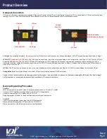
Compact Converters
CCUs and CCDs have a rectangular waveguide RF port and a coaxial LO and IF port. The drawing for a typical CCU is shown below. CCD has similar ports and
labeling. Older CCU and CCD modules may have different form factors, E-field polarization or ports in different locations.
LO Input:
For optimal performance, the user must adjust LO power at each frequency for optimal performance. DO NOT exceed damage limits listed on Page 7.
IF Port (
ESD Sensitive for CCUs only
):
The IF port can be used as an input or an output depending on the configuration (see Page 4). The IF port for CCUs is
extremely ESD sensitive. The IF port for CCDs has ESD protection. DO NOT apply any DC biases or surges when connecting / disconnecting from IF port.
Discharge static from cables before connecting to the device. DO NOT exceed damage limits listed on Page 7. Replace IF port with provided 50
Ω termination
when IF port is not in use.
RF Port:
The RF port can be used as an input or an output depending on the configuration (see Page 4). DO NOT exceed damage limits listed on Page 7.
Voltage Bias Port:
The voltage bias port pr9V that is used to bias external VDI RF amplifiers.
Failure to follow these procedures may damage or destroy the device. The user is liable for repair costs of detectors damaged by ESD, and the use of stringent
ESD precautions is recommended when making connections to VDI compact converters.
General Operating Procedure
Turn On:
With the input power turned off, make all necessary connections (i.e. LO cable, IF cable).
Connect VDI RF amplifier to Voltage Bias Port of CCU/CCD (if applicable).
Connect power supply to DC Power port on CCU/CCD.
Apply appropriate LO power to the device then apply small signal input power.
Turn Off:
Turn off small signal input power then turn off LO input power.
Disconnect power supply from DC Power port on CCD/CCD.
Disconnect and turn off all other equipment on user test bench.
Product Overview
RF Port
LED (ON/OFF)
DC Power
LO Input
IF Port
Voltage
Bias Port
E-Field Polarization
[Horizontal Polarization is shown]
Sec-2
Pg-5


