background image


-


16


FORCE CONTROLLED WARTHOG - USER'S MANUAL V1.0 

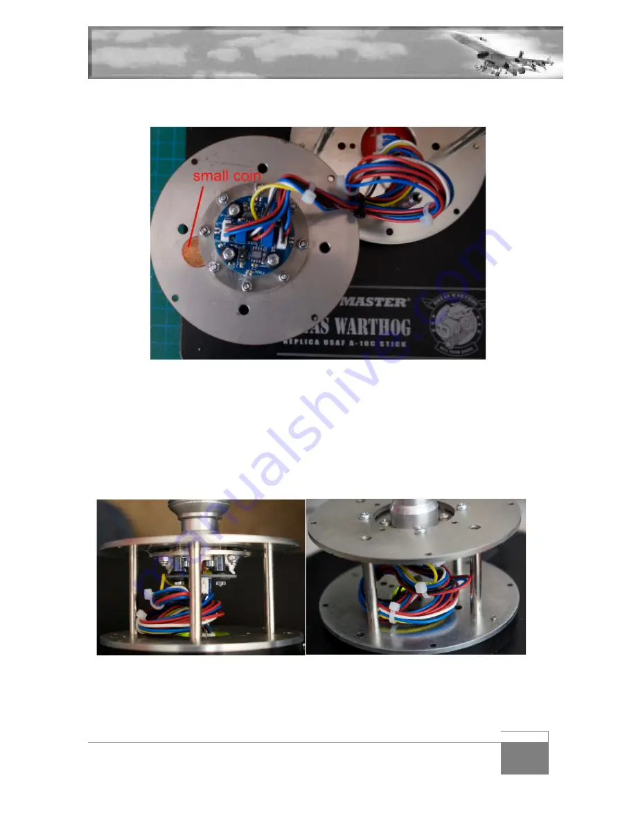
A good tip is to insert a coin between the two plates and screw the nylon bolts in. This will give a 
good reference for tightening the bolts in. 


The PCB is printed with the word FRONT this will be very handy in the next couple of minutes. Slide 
the black cylinder casing on the base and align it with the 4 notches.  
Connect the 3 connectors to the base PCB while supporting the PCB from under with your finger as 
you plug them in. Make sure you match Y with Y and X with X. It’s also referenced on both PCB so if 
you mess it up, it’s because you didn’t read    
Secure the wires in place with the supplied cable zips, it’s important that the cables are not severed 
as you screw the base closed. Here are pictures helping you see how the cables are supposed to be 
placed inside the base: 


Summary of Contents for FCW

Page 1: ... 1 FORCE CONTROLLED WARTHOG USER S MANUAL V1 0 FORCE CONTROLLED WARTHOG FCW Installation s manual ...

Page 2: ...ling the Warthog FCW into other bases 19 3 1 Cockpit base 19 3 2 Cougar base 19 4 Setting up your FCW 20 4 1 Electronic Calibration 20 4 2 Installing the software 22 5 Using your FCW 25 5 1 Changing options through software 25 5 2 Changing options through stick button combinations 28 6 Programming your FCW 30 7 Contacts and credits 31 ...

Page 3: ...o reason that the FCW cannot be installed with a Cougar The FCW is indeed backwards compatible with the Cougar If you do install the FCW in a cougar be aware that you will lose the possibility to connect the rudder and throttle on the cougar stick base You must seek a way to connect the rudder and throttle independently I hope you enjoy using your FCW as much as I enjoyed designing building and us...

Page 4: ...components in a small box while you are working Turn the base over and unscrew the flat plate from the warthog base That will separate the base from the plate and give you access to the warthog TM pcb Let s start by removing this from the warthog As you see on the following pictures the base I used for this manual is one of the early warthog prototype and is not grounded Chances are high that your...

Page 5: ...onnector and a black line over the second Remove the connectors by gently separating with a flat screwdriver and pull them away Unscrew then the 2 small PCB screws and store them away you might need them later on You can now remove the Warthog PCB and it s cable from the warthog base Needless to say it s precious store it securely away Turn the base over and unscrew the round metal plate held in p...

Page 6: ...h the 4 screws marked in red on the following picture that spring will extend unless you hold the plate firmly in place until all screws are out Please make sure you don t unscrew the last one unless you re pushing the plate down Failure to do so may damage the screw thread and create problems when you attempt to reassemble the base ...

Page 7: ... V1 0 I didn t lie to you that spring is huge Remove the top plate and remove the spring by lifting it up from the base Be careful the spring may be full of grease You can now lift the cylinder casing It s simply pinned in the base with 4 pins ...

Page 8: ... are held in place with the 4 silver screws of which you may already have unscrewed 2 when removing the ground wire before Before unscrewing them all 4 you may also unscrew the centre light grey piece held in place with the 2 smaller screws The grey part can be lifted up or flip the base so gravity can help ...

Page 9: ...is ready for the FCW Once again make sure you stow securely away the left over from the warthog you may need them one day to help a fellow virtual pilot The next thing we need to do is to secure the FCW PCB inside the Warthog base This is the only intrusive modification to your hardware Although the PCB takes the place of the old Thrustmaster PCB it does feature a mini USB port that needs to go th...

Page 10: ... thing to do is to mark the cuts I used tape but a pen works equally fine Saw alongside the tape vertically until you meet the flat bottom don t go all the way through the plastic touching the metal Stop when the connector has enough room to slide through Repeat on the other side alongside the other piece of tape Cutting the horizontal part is a bit more difficult but here is a modalism trick Usin...

Page 11: ... plastic models Then PCB can now be placed flat over it s supporting holes The FCW kit doesn t provide new screws and expect you to re use the original ones to screw the PCB in place Flip the base and we re ready to reassemble the base If you do not want to cut your warthog base you can modify the red PCB to reuse the warthog USB cable Please be aware this modification is done at your own risk and...

Page 12: ... 12 FORCE CONTROLLED WARTHOG USER S MANUAL V1 0 Here is the result after the cut 2 Unsolder the USB cable 5 wires from the original warthog PCB ...

Page 13: ... FORCE CONTROLLED WARTHOG USER S MANUAL V1 0 3 Insert the 5 wires of the USB cable into the red FCW PCB following the order seen in the picture below 4 Flip the PCB on the other side and solder all 5 wires ...

Page 14: ... 14 FORCE CONTROLLED WARTHOG USER S MANUAL V1 0 5 Place the PCB into the base with the usb cable through the original opening ...

Page 15: ...te centre screw holes and slide the O rings on the other side of the support plate Then insert the FCW through the hole on the side of the o rings and match all screws with the FCW holes You can now bolt each screw using the provided nylon secured bolts Do not overtight them They have to be secure but they won t unscrew anyway thanks to the nylon washer included in the bolt ...

Page 16: ...casing on the base and align it with the 4 notches Connect the 3 connectors to the base PCB while supporting the PCB from under with your finger as you plug them in Make sure you match Y with Y and X with X It s also referenced on both PCB so if you mess it up it s because you didn t read Secure the wires in place with the supplied cable zips it s important that the cables are not severed as you s...

Page 17: ...set both dip to off if you intend to use the mod with a Cougar Response curves are slightly better with the warthog settings but You have 4 possibilities to orient the base according to your exit cable The FCW PCB tells you where the front is another option is to screw the warthog handle in place By rotating the top plate by 45 you can make the cable exit to the front the left the right or the rea...

Page 18: ...ith the 4 small notches then with the 4 supporting poles and screw it securely with the 4 black original screws Screw the large flat plate from under the base you will need it and replace your Warthog handle in place Connect a mini USB cable to the FCW warthog PCB That s it the FCW warthog installation is finished ...

Page 19: ... placed anywhere under the right auxiliary console at cable length So installation is even easier than in a warthog base 3 2 Cougar base As said earlier the FCW is backward compatible with the Cougar Installation in the cougar base is possible with the adapter plate which can be ordered along the FCW PIX To install the FCW into a Cougar base please refer to the FCC manual Bear in mind that if you ...

Page 20: ...t will confirm each axis is centred These leds are placed on the connector side and are labelled Centre_X and Centre_Y These leds are visible with the PCB screwed in the base by looking through the warthog base from the top Each axis also features a potentiometer with an adjustable screw on top These potentiometers are located on the FCW round pcb attached to the stick base ...

Page 21: ...for both axis Connect the FCW to the computer Turn slowly the adjusting screw until the relevant led turns green to indicate a centred axis Repeat for the other axis Once both leds are on the FCW is electronically centred Please note it s an electronic calibration so it does not matter the position of the weight applied to the stick You can perform this calibration with the stick mount in any posi...

Page 22: ...ptions can be set with button press combinations for further information read the chapter using your FCW The supplied software is mainly a Graphic User Interface GUI that gives you another way of setting up the Warthog FCW and update it s firmware Unzip de installer package in a temporary folder and launch the fcc_configurator_0 1 3 2 msi file Windows may block the execution of the file you may ov...

Page 23: ... 23 FORCE CONTROLLED WARTHOG USER S MANUAL V1 0 Choose an installation folder Installation is complete ...

Page 24: ...ed firmware software and the availability of a new one When you update always update the firmware first if both are available Click the Update firmware button A DOS windows will open and the firmware will be automatically updated The two versions number will match after a successful update Click the Update Software button The software will close and you will prompted for a new installation Follow ...

Page 25: ... options can also be changed on the fly without the use of the software by pressing a few buttons combination We will come back to that later The Sensitivity Settings allows you to either choose one of three defined forces 4 5 Kgf 10 Lbf 6 Kgf 13 Lbf 9 Kgf 20 Lbf Or a custom setting which is set through the user defined force setting option boxes mind the unit ...

Page 26: ...to emulate an analog FLCS or a digital FLCS There is no one fits all SSC in the real F 16 The sidestick controller was updated often along the operational life of the F 16 and force settings and ratio have been modified accordingly The nominal value of the ratio is the full pitch up command maximum required force Pitch down and roll forces are emulated with a certain ratio of the above pitch up re...

Page 27: ...kpit position Once you have set all options to your liking click the Apply Config button Settings will then be transferred to the device The Read and Save Settings button is used to sync the settings between the FCW and the GUI It will read the settings from the FCW and save them in the GUI As you may have noticed the GUI tells you which current setting is enabled in the device with a green dot or...

Page 28: ... It will exit right after one button press Basically you enter config mode and activate the option you like with the button press listed below After that config mode is exited and if you need to set another option you will have to re enter config mode again Do not expect to remain in config mode until you manually exit it The idea is to have in game access to quick change of the options in case on...

Page 29: ...he TMS switch will manage the FLCS emulation TMS left will set Analog FLCS TMS right will set Digital FLCS TMS down will disable FLCS emulation The DMS switch will manage the sensor rotation DMS left will disable sensor rotation DMS right will enable sensor rotation DMS up will set centre positions DMS down will exit config mode Second trigger detent will restore the settings to default value ...

Page 30: ...r programming capability Your only way to assign function to the stick is to use DirectX programming In most cases this is very simple as it all comes to select a function in the sim user interface and press the corresponding button on your stick For advanced function like DirectX shifting capabilities please refer to your favourite sim documentation ...

Page 31: ...ions about your FCW should be directed to this email address info vipercore nl Project Manager Designer Arend White Eagle Van Oosten Software Manager Uri Uri_ba Ben Avraham FCW Manual Alpha Beta tester Olivier Red Dog Beaumont Beta tester Jochen Sneakpeek Schmich Jorge Mr Well Pozo ...

Reviews: