background image


45

ETB Command Talk-Back & Public Address System

Installation & Operation Manual

A100K11162 v1

terminals 3-4, check that power failure contact labeled NC 6-7 is 

activated.

 -

Disconnect cables to + and – on the power supply module and 

check if the auto switch relay switches over to emergency 24V DC. 

On terminals 3-4, check that power failure contact labeled NC 6-7 

is activated. 

Substations

1. 

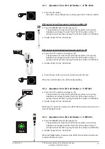
Operation from STB-1  (section 3.6.1) 

2. 

Operation from STB-2  (section 3.6.2) 

3. 

Operation from STB-3  (section 3.6.3) 

4. 

Operation from STB-5  (section 3.6.4) 

5. 

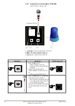
Operation from STB-5GN  (section 3.6.5) 

6. 

Operation from HE-112M/HE-112M-T  (section 3.6.6) 

7. 

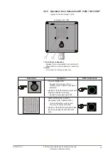
Operation from VH-10M/VH-10M-T  (section 3.6.7) 

8.  Operation from VHM-10/VHM-10-T  (section 3.6.8)

9. 

Operation from NEBB-42EX / EX Loudspeaker  (section 3.6.9) 

Volume Control


● Adjust sound pressure level to convenient level if necessary for 

master volume lines 1-5 and 6-10. 

 -

See section 2.6 and drawings in 

Section 7


Summary of Contents for 3005020018

Page 1: ...Command Talk Back Public Address System ETB 5 ETB 10 ETB 10A ETB 100 ETB 100A A100K11162 v1 TECHNICAL MANUAL...

Page 2: ...ETB 5 ETB 10 A100K10868 and ETB 100 A100K10867 Related Documentation Doc no Documentation A100K11163 ETB Command Talk Back PA User Guide Rules Regulations The ETB 5 ETB 10 ETB 10A ETB 100 ETB 100A sy...

Page 3: ...13 2 2 1 ETB Central Unit Amplifier Cabinet RS 3C 13 2 2 1 1 Identification Label for ETB Central Unit 13 2 2 2 Substations Other Equipment 13 2 2 2 1 Identification Label for Substation 13 2 3 Place...

Page 4: ...ssioning 43 4 1 General 43 4 2 Mechanical Inspection 43 4 3 Cable Inspection 43 4 4 Check Configurations 43 4 5 Identification Labels 43 4 6 Starting Up the System 44 4 7 Functions Test Procedure 44 5...

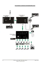
Page 5: ...DIN standard and fit neatly into integrated bridge solutions 1 1 ETB 10 System Configuration 1 10m cable EEx de IIC T6 PTB Nr Ex 87 B 1009 Ui 690V CEAG GHG 411 IN 16A Parallel station STB 6GN Parallel...

Page 6: ...tion STB 3 Line 9 Substation STB 1 Line 1 Substation STB 2 Line 3 Substation HE 112MT Line 4 100V EX Loudspeaker Parallel Station STB 6 Parallel Station SB 4 EX Call Box HAS 1 ETC STB5 VML 1520 P 66 P...

Page 7: ...ord and plug 3005020029 VPA 120 120W Power amplifier for ETB 100 ETB 100A 3005010235 VPA 240 240W Power amplifier for ETB 100 ETB 100A 3005010237 VPA 400 400W Power amplifier for ETB 100 ETB 100A 3005...

Page 8: ...for ETB 5 ETB 10 ETB 100 3005020065 STBOKS5 Wall mounted backbox for STB 5 STB 5GN 3005010206 STBOKS Wall mounted backbox for STB 6 STB 6GN 3005020064 SPS 4 Power supply 115 230V AC 24V DC w automatic...

Page 9: ...on to the ETB central unit Activation is indicated by a flashing green LED in the respective line button and a call tone from the panel speaker 1 5 6 Parallel Communication Operation of the ETB centra...

Page 10: ...switch U2410 1 5 10 Privacy Function STB 1 Substation STB 1 is designed for indoor use such as cabins mess rooms etc It is also equipped with a privacy function When the privacy function is enabled it...

Page 11: ...anel Press the button to increase the volume Press the button to decrease the volume 1 5 15 Power Supply SPS 4 Option The power supply SPS 4 is designed with power failure contact and automatic switch...

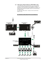
Page 12: ...18 Emergency Public Address ETB 100A only In order to comply with PA requirements the ETB 100A system is designed with a minimum of two PA call stations for Emergency PA for all lines Call station 1...

Page 13: ...e flush or bulkhead mounted in a normal and ventilated indoor environment with a temperature of maximum 55 C Make sure that there is sufficient space for cables and maintenance 2 2 1 1 Identification...

Page 14: ...tion Operation Manual 2 4 Terminal Configurations Pluggable screw terminals for cables of max 2 5 mm2 are utilized Refer to technical drawings in section 7 Connection Block Single Line Diagrams for mo...

Page 15: ...System Installation Operation Manual A100K11162 v1 2 4 2 ETB 5 ETB 10 Terminal Configurations on PCB Terminal block C1 C10 ETB 100 ETB 100A only No 1 2 for substation line low impedance No 3 4 for sub...

Page 16: ...2 ETB 100 ETB 100A only Muting of external alarm system Terminal block K1 ETB 100A only Located on PCB labeled ETB ALL SUB For connection to Emergency PA station No 1 2 audio No 3 4 switch No 5 screen...

Page 17: ...ions requires another sound pressure level this can be changed to the desired audibility and volume 2 8 Extra Signal Device The maximum load for each substation line is 50 mA to substation with relay...

Page 18: ...hout talk back Jumper marked J12 to J21 for each line on ETB 100 board have to be set in position PA 3 12 Substation STB 1 Default setting is Privacy function can be set to normal Talk Back Function T...

Page 19: ...aker For communication and alarm signals 2 Line Buttons Lines 1 5 for ETB 5 Lines 1 10 for ETB 10 ETB 10A and ETB 100 ETB 100A 3 Green LED Indication light for each line button 4 Microphone Connector...

Page 20: ...The central unit will be in listening mode as soon as a station is selected To terminate the communication press the selected line button again The LED will stop being lit to indicate that the select...

Page 21: ...l unit can switch off and terminate the call Press the required line buttons The call is set up indicated by the LEDs lighted a steady green in the selected buttons Press the SIGN button A tone signal...

Page 22: ...ed to the selected station as long as the SIGN button is kept pressed This will also activate a signal to substations equipped with extra signal devices ETB central unit with gooseneck microphone MB 3...

Page 23: ...removed for this function 3 1 5 Sending Signal to Substations with Extra Signal Devices Substations STB 3 STB 5 and STB 5GN are equipped with a relay for activating extra signal devices An extra sign...

Page 24: ...by a steady green LED ETB central unit with gooseneck microphone MB 30G Press the TALK button Speak clearly into the microphone When the TALK button is released the ETB will be in listening mode and...

Page 25: ...EDs the calls are set up indicated by a steady green LED The ETB central unit can select between substation lines and terminate calls by pressing the respective line buttons once more ETB central unit...

Page 26: ...y the ETB central unit The bridge wing unit will be in operation mode as soon as a station is selected on the ETB central unit 3 PTT Switch 1 2 1 Parallel to central unit 2 For microphone 3 Loudspeake...

Page 27: ...signal devices Parallel Station STB 6 with Handheld Microphone Ingress Protection Rating IP44 Press the PTT switch on the handheld microphone ETC 1 TB Speak clearly into the microphone When the PTT s...

Page 28: ...phone Horn Loudspeaker Ingress Protection Rating IP66 The parallel station comprises the SB 4 Plug box P 66 microphone and VML 1520 horn loudspeaker Press the PTT switch on the handheld microphone P 6...

Page 29: ...substations and in the ETB 10A central unit To override the function using ETB 10A with gooseneck microphone MB 30G Press the TALK button on the ETB 10A central unit Speak clearly into the gooseneck...

Page 30: ...e Call Press the line button The call is set up indicated by a steady green LED Group Call Press the required line buttons The call is set up indicated by the LEDs lighted a steady green in the select...

Page 31: ...ations The configuration comprises an ETB 100A central unit with and call stations VMP 603 or VMT 603 The operation will mute the General Alarm system and override Talk Back and single PA calls The ET...

Page 32: ...B Command Talk Back Public Address System Installation Operation Manual PA Call Stations Configuration with Handheld Microphone VINGTOR PA Call Station 1 ETB 100A PA Call Station 3 VMP 603 PA Call Sta...

Page 33: ...ng PA calls from station 2 VMT 603 Speak clearly into the microphone Press the ALL button once more to terminate the PA call When the call terminates the LED will stop lighting 3 5 2 Operation from PA...

Page 34: ...for communication to central unit 2 Push button switch for call to central unit 3 PTT switch for talk to central unit Loudspeaker CALL TALK Substation STB 1 Substation Operation ETB Central Unit Press...

Page 35: ...ker Substation STB 2 Substation Operation ETB Central Unit Press the CALL button Indicated by flashing green LED for substation line and a signal in the ETB panel loudspeaker Operator of the ETB press...

Page 36: ...in the loudspeaker if installed Operator of the ETB central unit terminates the call by pressing the line button once more With microphone P 66 PTT Switch Press the PTT switch on the microphone Speak...

Page 37: ...rminates the call by pressing the line button once more With handset HAS 1 PTT Switch Press the PTT switch on the handset Speak clearly into the handset When the PTT switch is released the STB 5 will...

Page 38: ...n STB 5GN Substation Operation ETB Central Unit Press the CALL button Indicated by flashing green LED for substation line and a signal in the ETB panel loudspeaker Operator of the ETB presses the resp...

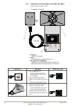
Page 39: ...er CALL Substation HE 112M Substation Operation ETB Central Unit Press the CALL button Indicated by flashing green LED for substation line and a signal in the ETB panel loudspeaker Operator of the ETB...

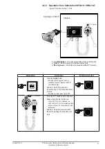
Page 40: ...ETB presses the respective line button and the call is set up Indicated by steady green light in ETB Speak clearly into the re entrant horn speaker of VH 10M VH 10M T The same loudspeaker is used to s...

Page 41: ...eration ETB Central Unit Press the CALL button Indicated by flashing green LED for substation line and a signal in the ETB panel loudspeaker Operator of the ETB presses the respective line 1 10 button...

Page 42: ...ETB panel loudspeaker Operator of the ETB presses the respective line 1 10 button and the call is set up Indicated by steady green light in ETB Speak clearly into the re entrant EX loudspeaker The sa...

Page 43: ...able is 0 75 mm2 and connected to terminal block K11 to terminal 1 to terminal 2 The screen is grounded on terminal 3 0 75 mm2 cable is used for power to signal units Polarity for extra signal device...

Page 44: ...5 Make a call to a group of substations section 3 1 2 6 Make All Call section 3 1 3 7 Give signal to substations with extra signal device section 3 1 5 8 Receive a Call from an substation section 3 1...

Page 45: ...vated Substations 1 Operation from STB 1 section 3 6 1 2 Operation from STB 2 section 3 6 2 3 Operation from STB 3 section 3 6 3 4 Operation from STB 5 section 3 6 4 5 Operation from STB 5GN section 3...

Page 46: ...xtension is OK the substation has to be repaired Operation problem from a substation Continuous beeping tone in the ETB central unit Change polarity in substation terminals no 1 2 No signal in substat...

Page 47: ...extension number If problem persists substation has to be repaired If substation operation is OK ETB central unit has to be repaired High background sound Due to nearby substation 1 Replace current su...

Page 48: ...48 A100K11162 v1 ETB Command Talk Back Public Address System Installation Operation Manual 6 Dimension Drawings All dimensions shown are in mm 6 1 ETB 5...

Page 49: ...49 ETB Command Talk Back Public Address System Installation Operation Manual A100K11162 v1 6 2 ETB 10 ETB 10A...

Page 50: ...50 A100K11162 v1 ETB Command Talk Back Public Address System Installation Operation Manual 6 3 ETB 100 ETB 100A...

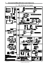
Page 51: ...mand Talk Back Public Address System Installation Operation Manual A100K11162 v1 7 Connection Block Single Line Diagrams 7 1 ETB 100 Single Line Diagram Zenitel Marine Zenitel Marine Norway VMT 603 VM...

Page 52: ...52 A100K11162 v1 ETB Command Talk Back Public Address System Installation Operation Manual 7 2 ETB 5 ETB 10 Single Line Diagram Zenitel Marine Zenitel Marine Norway...

Page 53: ...53 ETB Command Talk Back Public Address System Installation Operation Manual A100K11162 v1 7 3 ETB 100 PCB Layout...

Page 54: ...54 A100K11162 v1 ETB Command Talk Back Public Address System Installation Operation Manual...

Page 55: ...55 ETB Command Talk Back Public Address System Installation Operation Manual A100K11162 v1 7 4 ETB 5 ETB 10 PCB Layout...

Page 56: ...56 A100K11162 v1 ETB Command Talk Back Public Address System Installation Operation Manual...

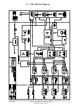
Page 57: ...57 ETB Command Talk Back Public Address System Installation Operation Manual A100K11162 v1 7 5 ETB 100 Block Diagram...

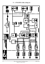
Page 58: ...58 A100K11162 v1 ETB Command Talk Back Public Address System Installation Operation Manual 7 6 ETB 5 ETB 10 Block Diagram...

Page 59: ...59 ETB Command Talk Back Public Address System Installation Operation Manual A100K11162 v1 7 7 ETB 100 Cable Connection Diagrams...

Page 60: ...60 A100K11162 v1 ETB Command Talk Back Public Address System Installation Operation Manual...

Page 61: ...61 ETB Command Talk Back Public Address System Installation Operation Manual A100K11162 v1...

Page 62: ...62 A100K11162 v1 ETB Command Talk Back Public Address System Installation Operation Manual...

Page 63: ...63 ETB Command Talk Back Public Address System Installation Operation Manual A100K11162 v1 7 8 ETB 5 ETB 10 Cable Connection Diagrams...

Page 64: ...64 A100K11162 v1 ETB Command Talk Back Public Address System Installation Operation Manual...

Page 65: ...65 ETB Command Talk Back Public Address System Installation Operation Manual A100K11162 v1...

Page 66: ...66 A100K11162 v1 ETB Command Talk Back Public Address System Installation Operation Manual...

Page 67: ...67 ETB Command Talk Back Public Address System Installation Operation Manual A100K11162 v1...

Page 68: ...enitel Norway AS The company s Quality Assurance System is certified to meet the requirements in NS EN ISO 9001 2008 Zenitel Norway AS reserves the right to modify designs and alter specifications wit...

Reviews: