Viking VUIM/DUIM150 Service Manual Download Page 25

© 2009 Viking Preferred Service 

25

Removing Drain Valve

1.   Drain water in the reservoir by removing the 

drain plug or switching to the “CLEAN” switch 
position and then to the “OFF” position. 
Replace the drain plug, if this method is used, 
after the water has been drained.

2.   Disconnect power, water line, and drain line. 

If a drain pump is used, it will need to be 
disconnected and removed.

3.   Remove the back panel and lower shroud  

(see 

Figure 6

).

4.   Remove the brown wire and white wire at the 

drain valve terminals.

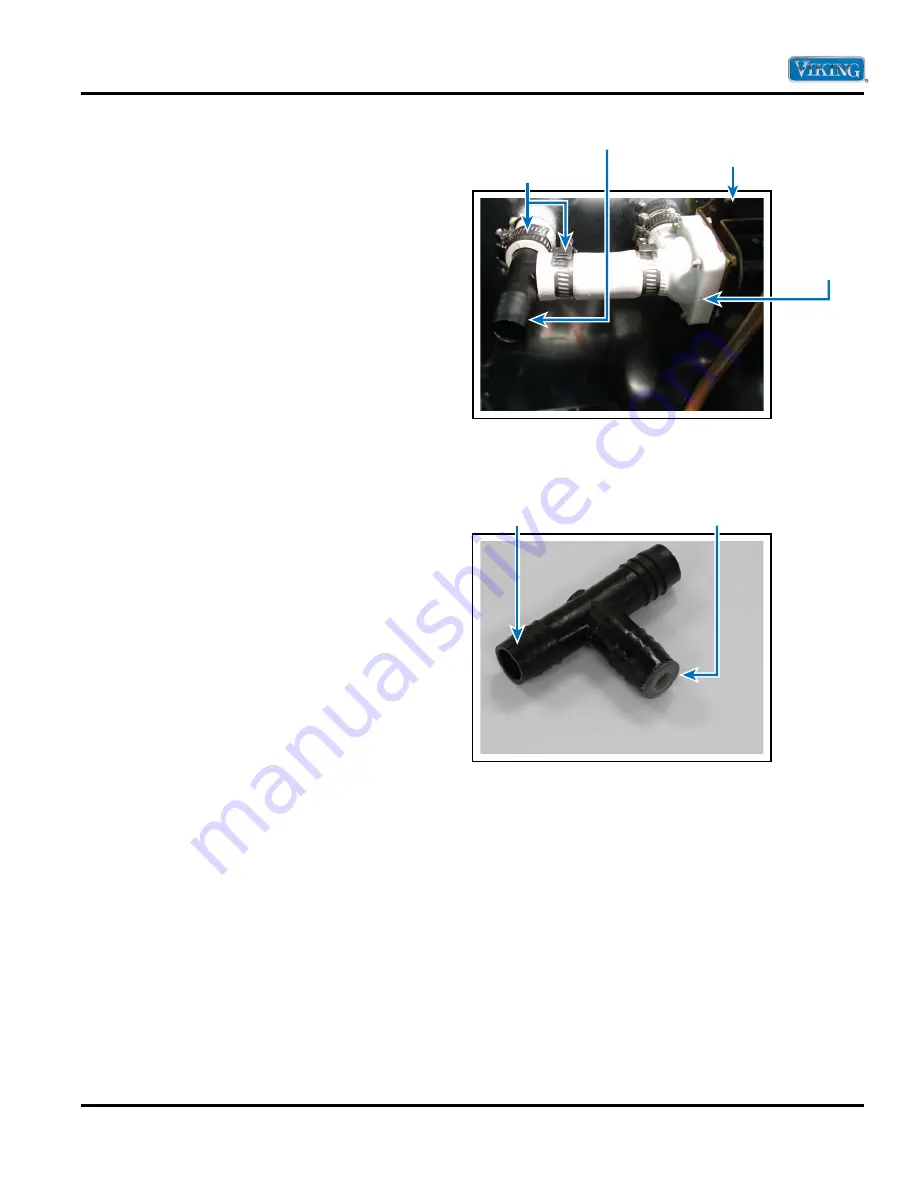
5.   Loosen the hose clamps on each side of the 

drain valve (see 

Figure 12

).

6.   Remove the two screws securing the drain valve 

(see 

Figure 12

).

7.  Remove the drain valve.

Installing Drain Valve

Reverse the removal procedure for installation 
(see above). It is important to keep the valve clean 
during installation to assure proper performance. 
After installation, make certain the hose clamps are 
secure and that the valve or tubing does not leak. 
This can be done by adding water to the reservoir 
and observing for any leaks from the tubing 
connections or the valve itself. Also, at this time, 
make certain that the drain tee-fitting flow restrictor 
is in place (see 

Figure 13

). Reposition as needed or 

order replacement.

Hose clamps

Figure 12

Screw

Drain fitting tee

Drain valve

Figure 13

Drain fitting tee

Drain flow restrictor 

in this location

Service Diagnostics and Procedures 

(Valves)

Summary of Contents for VUIM/DUIM150

Page 1: ...G AFTER 3 2007 VUIM DUIM153 Professional and Designer Undercounter Freestanding 15 W Ice Machine Service Manual This manual is to be used by quali ed appliance technicians only Viking does not assume...

Page 2: ...eration in ON Position 12 Operation in CLEAN Position 13 SERVICE DIAGNOSTICS AND PROCEDURES Sealed System Introduction 14 Low Side Leaks 14 High Side Leaks 14 Restricted Capillary Tube 14 Access Valve...

Page 3: ...NG REPAIRS Pride and workmanship go into every product to provide our customers with quality appliances It is possible however that during the lifetime of a product service may be required Products sh...

Page 4: ...aser of the product warranted hereunder and to each transferee owner of the product during the term of the warranty This warranty shall apply to products purchased and located in the United States and...

Page 5: ...RTANT Retain proof of original purchase to establish warranty period The return of the Owner Registration Card is not a condition of warranty coverage You should however return the Owner Registration...

Page 6: ...9 cm 37 9 16 95 4 cm 25 5 8 65 1 cm 37 9 16 95 4 cm Approximate shipping weight 110 lbs 49 5 kg VUIM150 153 DUIM150 VUIM150 DL 24 5 8 62 6 cm 27 1 8 68 9 cm 22 55 9 cm 14 3 4 37 5 cm 34 1 4 87 0 cm m...

Page 7: ...should be referred to a qualified servicer Have the installer show you the location of the gas shut off valve and how to shut off in an emergency Electrical Requirements Check your national and local...

Page 8: ...t trim just above the toe grille or on the inner door liner The serial number will need to be given when inquiring about unit or ordering parts V U I M 1 5 0 S S Serial Number Month Assembly Site Day...

Page 9: ...protective safety glasses and gloves when working on any Viking product Any refrigerant whether CFC HCFC or HFC R 12 R 22 or R 134a must be recovered Federal regulationsprohibit intentional venting or...

Page 10: ...ing This tubing can be routed to a gravity drain in area shown in Figure 1 or to a remote gravity drain that is located below ice machine Be sure to check your local codes Slope any long horizontal ru...

Page 11: ...s for the harvest cycle The drain valve will energize The grid cutter will energize The hot gas valve will energize when the evaporator thermistor senses the harvest setpoint 11 0 F The hot gas valve...

Page 12: ...and then de energize after which water solenoid will energize for two minutes and then de energize Loads will remain in this state until evaporator thermistor temperature rises to production setpoint...

Page 13: ...he CLEAN Position IMPORTANT The assumptions before proceeding are water is supplied to ice machine see Section Water Requirements section proper electrical power supplied to ice machine see Electrical...

Page 14: ...bly must be ordered if the capillary tube is found to be plugged or severly restricted Restrictions cannot be flushed out 6 Be sure to purge the system after final brazing This will flush out any air...

Page 15: ...3 If it has been determined that there is proper contact between the thermistor and the evaporator plate the voltage at the thermistor terminals can be read The voltage can be read while the unit is r...

Page 16: ...with dirty nitrogen gas and evacuate to 400 microns before re charging THE METHOD FOR RE CHARGING THE UNIT IS BY WEIGHT USING VAPOR REFRIGERANT Using manifold gage set up hook up charge hoses to the a...

Page 17: ...taminated system or damage to the valve body will cause any of these failures Care in keeping the system clean handling of the valve keeping the valve cool during brazing and evacuation of the system...

Page 18: ...mechanical out the back of the unit just enough to gain access to the hot gas valve and drier assembly see Figure 10 9 Install system access valve s and recover refrigerant After recovering be sure t...

Page 19: ...Braze the hot gas valve tube from the bottom of the valve into the evaporator bypass tube 6 Cool the brazed joints with a damp cloth 7 Remove the heat sink or damp cloth from the valve body 8 Check f...

Page 20: ...joint Any cracks will break the proper thermal conductivity between the evaporator plate and the thermistor and result in a long production cycle with a thick slab on the plate The thermistor should b...

Page 21: ...stall the four rubber grommets in the bottom of the new compressor and install the two sleeves where the carriage bolts will be located Mount the new compressor and install the two washers and lock nu...

Page 22: ...e 6 3 Remove grille by removing the two or four screws depending on grille style and disconnecting the three wires to rocker switch 4 Remove drain valve see page 25 5 Remove water valve see page 26 6...

Page 23: ...om hot high pressure vapor from the compressor The most common trouble is lack of airflow from either a restricted intake or exhaust opening in the front of the unit Lint dust hair and dirt build up n...

Page 24: ...valve will only be open for a fixed time of 45 seconds during the beginning of the harvest cycle The drain valve fails by allowing water to flow into the drain during the ice production cycle leak by...

Page 25: ...two screws securing the drain valve see Figure 12 7 Remove the drain valve Installing Drain Valve Reverse the removal procedure for installation see above It is important to keep the valve clean duri...

Page 26: ...it takes to fill up a one quart container The time should be 60 seconds to get the 0 25 gpm specification of valve If it takes substantially less than 60 seconds check the water supply pressure to mak...

Page 27: ...water line and drain line If a drain pump is used it will need to be disconnected and removed 2 Remove the back panel and lower shroud see Figure 6 3 Remove the grille by removing the two screws and...

Page 28: ...that is know such as an ice bath and measure the resistance across the wire leads 3 Compare the recorded resistance with Resistance versus Temperature Chart If measured resistance falls outside the re...

Page 29: ...art making ice THE THERMISTOR MUST BE FULLY INSERTED INTO THE PLATED SENSING TUBE FOR PROPER DETECTION You will typically receive an assembly with the thermistor and plated tube already assembled IMPO...

Page 30: ...xiting clean mode LED flashes twice with one interval between flashes every 5 seconds Bin sensor open or shorted LED flashes three times with one interval between flashes every 5 seconds Bin sensor op...

Page 31: ...C replace the transformer Removing Transformer 1 Disconnect power water line and drain line If a drain pump is used it will need to be disconnected and removed 2 Remove back panel and lower shroud see...

Page 32: ...e cutter grid is good At any other resistance readings it will need to be replaced Check for continuity between terminals and the cutter grid s stainless steel frame If continuity is found check for w...

Page 33: ...r 5 Drain reservoir by removing drain plug located on bottom of reservoir 6 Remove the two screws and spacers that secure reservoir see Figure 20 7 Remove reservoir by lifting drain tube off reservoir...

Page 34: ...l impeller type pump The pump and motor are an assembly that cannot be repaired separately To check circulation pump with the pump removed Make sure motor shaft turns freely This can be done by rotati...

Page 35: ...ews that secure circulation pump see Figure 24 9 Remove circulation pump Installing Circulation Pump Reverse removal procedure for installation see above Cleaning Ice Machine 1 Remove all ice from ice...

Page 36: ...te See Cleaning Your Ice Machine section for cleaning the unit for proper operation Distributor tube is restricted or not installed correctly See Cleaning Your Ice Machine section for cleaning the uni...

Page 37: ...in lines If using a drain pump check the inlet screen discharge line and vent line for any build up or restrictions Leaking drain valve See Cleaning Your Ice Machine section for cleaning the unit This...

Page 38: ...the front of the unit is free and open for proper air circulation Check and clean the condenser coil by removing the grille in the front of the unit Clean the condenser with a vacuum and brush attachm...

Page 39: ...ion or improperly installed drain lines will cause water to back up into the ice bin Make certain there are no kinks or restrictions in the drain lines If necessary consult a qualified plumber Foreign...

Page 40: ...Check compressor with a start cord Evaporator Check evaporator to see if its getting frosted Compressor not running Low on charge leak Restriction Low voltage Hot Gas and Drain Solenoids the initial c...

Page 41: ...porator a typical harvest cycle then the hot gas valve is not opening See step A below A Check for voltage at solenoid Approx 120 when valve is energized Replace valve B Check resistance of solenoid c...

Page 42: ...2009 Viking Preferred Service 42 Wiring and Schematics...

Page 43: ...2009 Viking Preferred Service 43 Wiring and Schematics...

Reviews: