4
Huskystar 207, 215
( A )
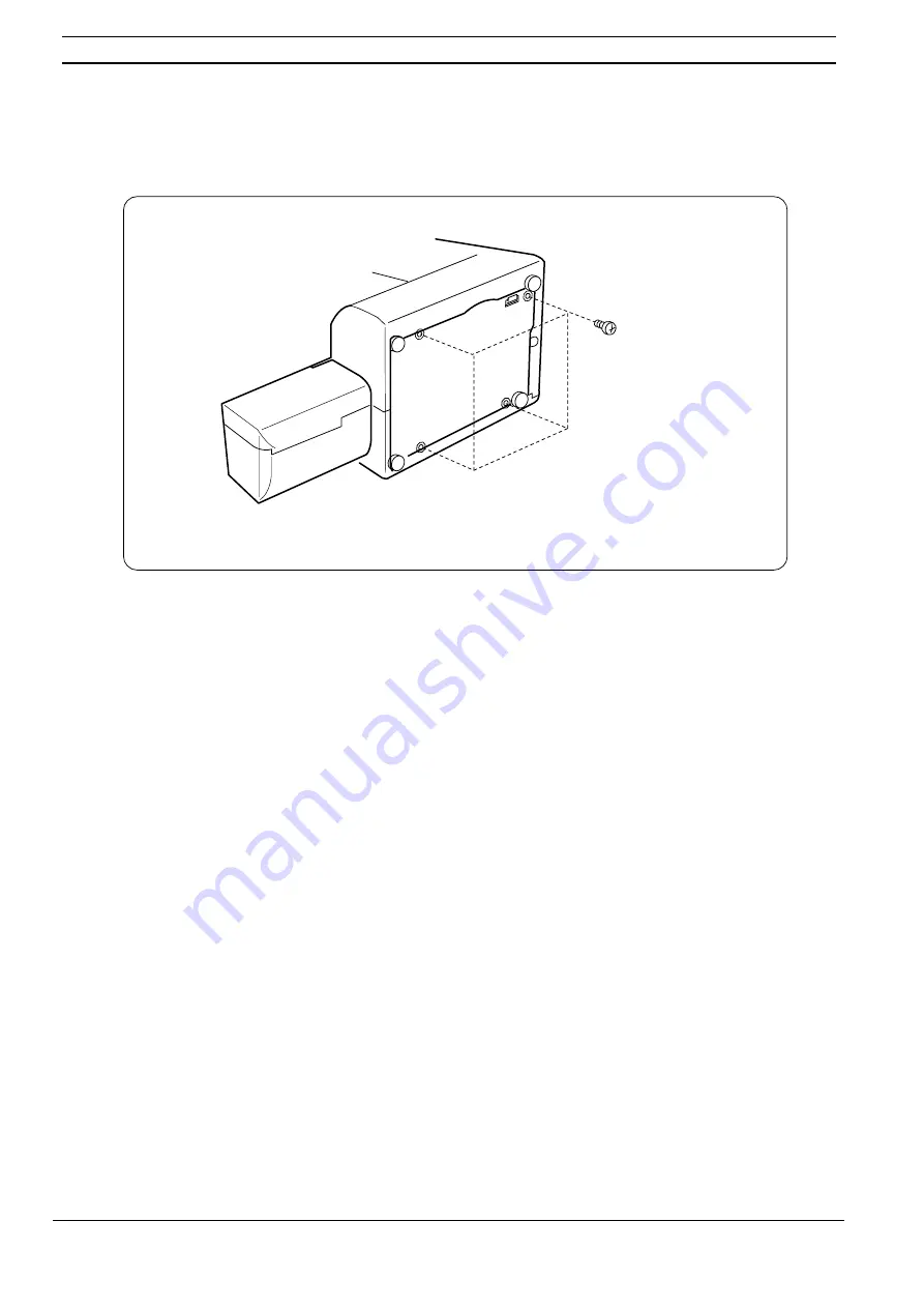
BASE PLATE
To remove.
1.
Remove 4 screws (A).
2.
Remove the base plate.
To attach.
3.
Follow the above procedure in reverse.
0DULQDV/LWWOH6KRSSHRQH%D\
Page 1: ...Huskystar 207 215 Typ B Service manual Printed and Made in Sweden Feb 2001 104 72 51 26...
Page 2: ...ARANCE BETWEEN NEEDLE AND HOOK ADJUSTMENT METHOD NO 1 Sewing head 12 CLEARANCE BETWEEN NEEDLE AND HOOK ADJUSTMENT METHOD NO 2 HOOK 13 FEED DOG HEIGHT 14 NEEDLE BAR HEIGHT 15 NEEDLE TIMING TO SHUTTLE 1...
Page 3: ...B A E To remove 1 Remove the face cover D by removing the cap A and screw B To attach 2 Attach the face cover D with the set screw B then attach the cap A 1 Loosen screw C 2 Take the motor cover away...
Page 4: ...4 Huskystar 207 215 A BASE PLATE To remove 1 Remove 4 screws A 2 Remove the base plate To attach 3 Follow the above procedure in reverse 0 DULQD V LWWOH 6KRSSH RQ H D...
Page 5: ...T COVER To remove 1 Remove the face cover and motor cover 2 Loosen set screws A B C D and then remove the front cover J by removing set screws E F and G Note Remove the hook H first then hook I To att...
Page 6: ...up the spool pins K Loosen set screws A B C and D 2 pcs then remove the rear cover I by removing the set screws E F G and H Note Remove the rear cover in the order of lower part X upper part Y and pre...
Page 7: ...tension spring The lower thread tension should be between 25 and 35 grams when pulling the thread in the direction of A Adjustment 1 If the lower thread tension is too tight turn the adjusting screw...
Page 8: ...direction of A with the tension dial at 3 The presser foot should be lowered when checking the upper thread tension Adjustment 1 Remove the front cover 2 Turn the adjusting nut B in the direction of C...
Page 9: ...crew B and take the lamp socket off 3 Raise the presser foot lever and loosen the hexagon socket screw C on the presser bar holder Adjust the distance between the zigzag foot D and the needle plate E...
Page 10: ...selector dial with maximum zigzag width and remove the front cover 2 Loosen the two set screws A 3 Adjust the needle swing by turning the hand wheel while holding the worm gear B so there is no rotat...
Page 11: ...e needle drop positions should be more than 0 2mm and equal C If not adjust as follows To adjust 1 Remove the face cover 2 Set the stitch selector dial at maximum zigzag width 3 Loosen the hexagon soc...
Page 12: ...in left position and zigzag dial at 0 4 Loosen set screw A and move the needle bar supporter E in the direction of the arrows to obtain the clearance between 0 05 to 0 10 mm F If the clearance is too...
Page 13: ...k between the lower shaft gear and hook drive gear Then tighten the hexagon socket screw A slightly 5 Lower the needle and loosen the two hexagon socket screws B Move the shuttle race unit axially eit...
Page 14: ...0 75 and 0 90mm C To adjust 1 Open the bed cover plate 2 Lower the zigzag foot and turn the hand wheel toward you until the feed dog comes to its highest position 3 Loosen the hexagon socket screw A 4...
Page 15: ...C To adjust 1 Remove the face cover 2 Set the stitch selector dial at for Model 207 For Model 215 set it at and zigzag dial at 0 3 Open the bed cover plate 4 Remove the shuttle race ring 5 Turn the ha...
Page 16: ...ion and zigzag width at 0 2 Remove the base plate 3 Open the bed cover plate 4 Remove the shuttle race ring 5 Turn the hand wheel towards you until the tip of the shuttle hook meets the left side of t...
Page 17: ...to 12 stitches in the backward feeding right side row paired with 10 stitches in the forward feeding left side row is considered acceptable To adjust 1 Sew a buttonhole 2 Remove the cap E by inserting...
Page 18: ...uttonhole adjust as follows To adjust 1 Set the stitch selector dial at and the stitch length dial at 4 2 Remove the front cover 3 Place a piece of paper under the foot and turn the hand wheel 4 Turn...
Page 19: ...s distorted when setting the stitch length dial at stretch adjust as follows To adjust 1 Remove the cap E by inserting a screwdriver into the notch F For Model 215 set it at stretchstitch and the stit...
Page 20: ...t zigzag stitching and stitch width dial at 5 3 Turn the hand wheel to bring the cam follower onto the top convex of the zigzag cam F 4 Loosen the screw C 5 Push the adjusting plate D to the direction...
Page 21: ...raight stitch needle in left position 4 Turn the hand wheel to bring the cam follower onto the top convex of the zigzag cam D 5 Loosen the set screw E 6 Push the adjusting plate F to the direction of...
Page 22: ...the front cover 3 Loosen the set screw A 4 Turn the hand wheel toward you until the cam follower B comes to the convex part of the zigzag cam C 5 Push the zigzag arm D until it touches the adjusting...
Page 23: ...se motor belt tension may cause jumping of the belt teeth on the motor pulley When pushing the motor belt with a finger at about 300 grams load C the deflection of the motor belt should be about 7mm t...
Page 24: ...star 207 215 B A C D B A E F F G E H 220 240V area 110 120V area Blue A With ridge E Brown B Without ridge F To Motor C To Motor G To Lamp D To Lamp H WIRING M a r i n a s L i t t l e S h o p p e o n...