


Square Gasket
(included)
Rectangle Gasket
(included)
E-1600A-MK-GNP
Mounting Plate
(included)
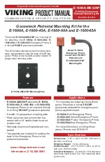
Installation
Step 1.
Adhere the square gasket to the
E-1600A-MK-GNP
mounting plate. Make sure gasket is
centered and holes align. (Figure 1)
Step 2.
Adhere the rectangular gasket to the other side of the
E-1600A-MK-GNP
mounting plate.
Make sure gasket is centered and holes and arrow symbol align. (Figure 1)
Step 3.
Place the
E-1600A
back plate on the rectangular gasket side of the
E-1600A-MK-GNP
mounting plate. Pull the wires through the center hole on the plates.
Make sure the arrow
symbol on the E-1600A-MK-GNP mounting plate is pointing UP
then attach the
square gasket side of the plate to the
VE-GNP
pedestal mounting plate with the 4 truss
head screws and nylock nuts as shown. Do not tighten screws until all 4 screws are in-
serted and plate is aligned. (Figure 2)
Step 4.
Attach the wires from the pedestal to the
E-1600A
with provided butt connectors then fas-
ten the
E-1600A
to mounting plate by tightening the set screw on the bottom of the unit.
Model E-1600A
(not included) see DOD# 215
(4) 10-24 Nylock nuts
included with mounting kit
E-1600A-MK-GNP Mounting Plate
with both gaskets adhered
(4) #10-24 x 5/8 Truss Head screws
included with mounting kit
VE-GNP
mounting plate
(not included)
see DOD# 424
E-1600A back plate,
included with model E-1600A
Figure 1
Figure 2
2