


Troubleshooting
©2010 Viking Preferred Service
13
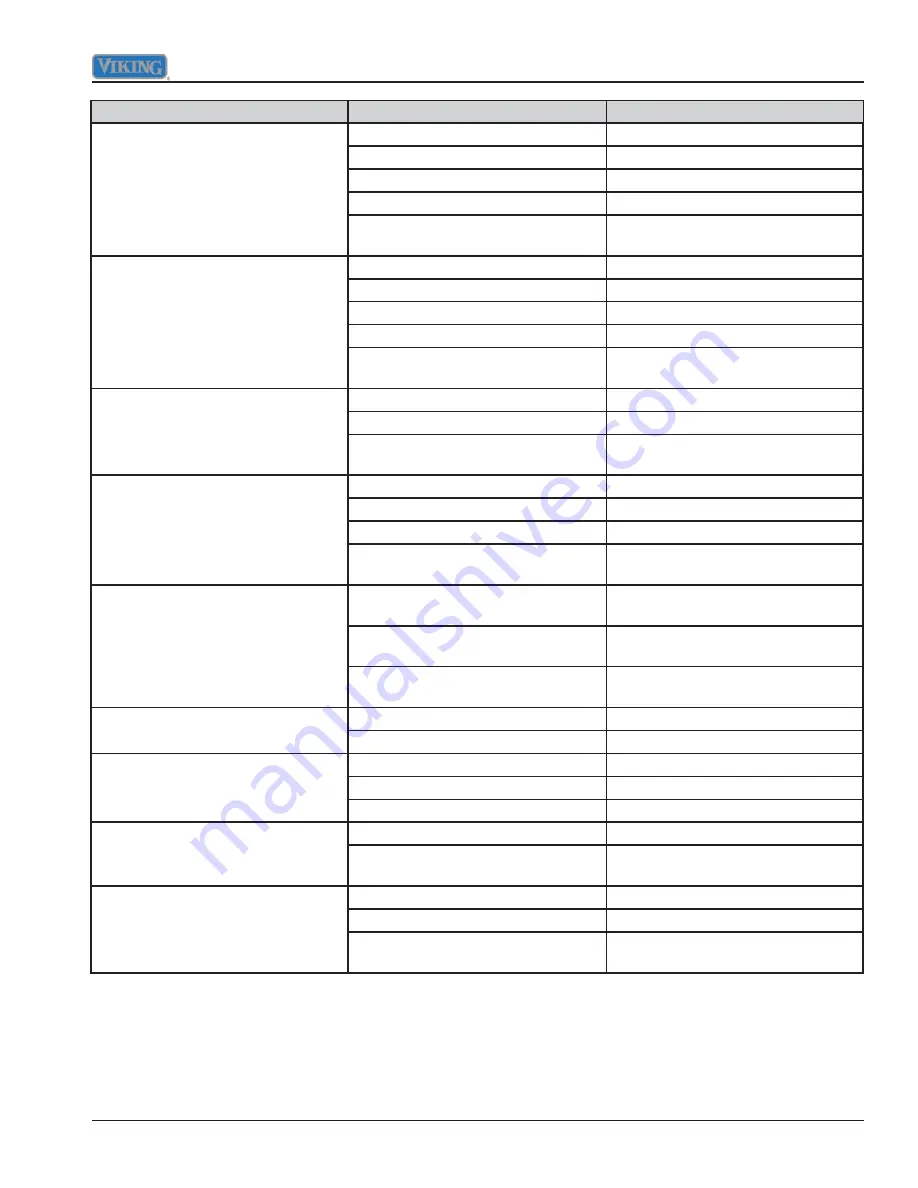
Symptom
Possible Cause
Corrective Action
Bake inoperable - broil, convection
fan, oven lights, and surface burner
igniters operate
Foreign objects/soil on igniter
Clean igniter and surrounding area
Open bake solenoid
Replace bake solenoid
Open oven control
Replace oven control
Open direct spark module
Replace direct spark module
Defective oven wiring (shorted,
open, or burned)
Repair or replace defective wiring
Broil inoperable - bake, convection
fan, oven lights, and surface burner
igniters operate
Foreign objects/soil on igniter
Clean igniter and surrounding area
Open broil solenoid
Replace broil solenoid
Open oven control
Replace oven control
Open direct spark module
Replace direct spark module
Defective oven wiring (shorted,
open, or burned)
Repair or replace defective wiring
Convection fan inoperable - bake,
broil, oven lights, and surface burner
igniters operate
Open convection fan switch
Replace convection fan switch
Open convection fan motor
Replace convection fan motor
Defective oven wiring (shorted,
open, or burned)
Repair or replace defective wiring
Oven lights inoperable - bake, broil,
convection fan, and surface burner
igniters operate
Open oven bulbs
Replace oven bulbs
Open light switch
Replace light switch
Open door light switch
Replace door light switch
Defective oven wiring (shorted,
open, or burned)
Repair or replace defective wiring
Surface burner igniters inoperable
- bake, broil, convection fan, oven
lights operate
Foreign objects/soil on igniter
Clean igniter and surrounding area
Open single point spark module
Replace single point spark module
Defective oven wiring (shorted,
open, or burned)
Repair or replace defective wiring
Igniters sparking but no
fl
ame
ignition
Gas supply valve is in “OFF” position Turn gas on
Gas supply is interrupted
Check regulator
Igniters sparking continuously after
fl
ame ignition
Power supply is not grounded
Check grounding
Power supply polarity is reversed
Check power source
Igniters are wet or dirty
Clean igniters
Burner ignites, but
fl
ame is large,
distorted, or yellow
Burner ports are clogged
Clean burner head
Unit is being operated on wrong type
of gas
Check gas type
Oven cycle light inoperable - bake,
broil, convection fan, oven lights,
surface burner igniters operate
Defective cycle light (neon)
Replace cycle light
Open oven control
Replace oven control
Defective oven wiring (shorted,
open, or burned)
Repair or replace defective wiring


