background image


 11

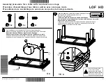
Step 3

Step 4

1.  Use Phillips M6 Screw


A  and Nut


B  to link between the 2 Cupboard Unit


5

  and Wall Cabinet 

1

.

2. Use Hex Bolt M6 Screw  C , D , E  to link between the Cabinet 

2

,

3

 and Wall

 Cabinet 

1

 as below diagram.

Summary of Contents for V6000-3

Page 1: ...les Assembly Manual V6000 3 V6000 3 AH ViGOR GmbH Am Langen Siepen 13 15 42857 Remscheid GERMANY 49 0 21 91 97 95 49 0 21 91 97 96 00 info vigor equipment com vigor equipment com Gebrauchsanweisung Mo...

Page 2: ...or equipment com vigor equipment com Unpacking 8 Assembly Tool Request 8 Exploded Drawing 8 Assembly Step 1 9 Step 2 10 Step 3 10 11 Step 4 11 Step 5 12 Finish 12 Auspacken 3 Anforderung Montagewerkze...

Page 3: ...tig auf Besch digungen pr fen die beim Transport entstanden sein k nnten Pr fen ob sich Teile gelockert haben fehlen oder besch digt sind Transportsch den sind gegen ber dem Spediteur geltend zu mache...

Page 4: ...ten Ort aufstellen und die Halterung 6 7 8 wie im Diagramm dargestellt unten anbringen Die Halterung wie unten markiert an der richtigen Position anbringen Die Halterungen sind beschriftet und k nnen...

Page 5: ...ollst ndig anziehen Soweit anziehen dass noch etwa 3 bis 5 Schraubenumdrehungen zum sp teren Anbringen der Schrankeinheit 5 verbleiben 2 Schrankeinheit anheben 5 und auf die Kreuzschlitzschraube M6 A...

Page 6: ...e M6 A und Mutter B verwenden um die beiden Schrankeinheiten 5 und den Wandschrank 1 miteinander zu verbinden 2 Sechskantschraube M6 C D E verwenden um den Schrank 2 3 und den Wandschrank 1 wie im Dia...

Page 7: ...rauben G und Distanzscheiben H am Werkbanksockel anbringen 2 Holzplatte 13 auf die Arbeitsfl che legen Oberste Schublade aus dem Schrank 2 entfernen und T r des Unterschranks 3 ffnen um die Holzschrau...

Page 8: ...tools for unpacking After unpacking unit inspect carefully for any damage that may have occurred during transit Check for loose missing or damaged parts Shipping damage claim must be filed with carri...

Page 9: ...the desired location and start to apply the Support Bracket 6 7 8 onto it as below diagram Apply the Support Bracket onto correct location as marked below Support Bracket will have labeling on it for...

Page 10: ...not tighten the Phillips M6 Screw A completely Have about 3 5 screw thread left in order to apply Cupboard Unit 5 later 2 Lift and hook the Cupboard Unit 5 to the Phillips M6 Screw A on the Support B...

Page 11: ...Step 3 Step 4 1 Use Phillips M6 Screw A and Nut B to link between the 2 Cupboard Unit 5 and Wall Cabinet 1 2 Use Hex Bolt M6 Screw C D E to link between the Cabinet 2 3 and Wall Cabinet 1 as below dia...

Page 12: ...ce Remove the top drawer on the Cabinet 2 and open the door of the Closet Cabinet 3 to screw in the Wooden Screws F from inner side into the wood plate Step 5 Finish ViGOR GmbH Am Langen Siepen 13 15...

Reviews: