background image


CAUTION


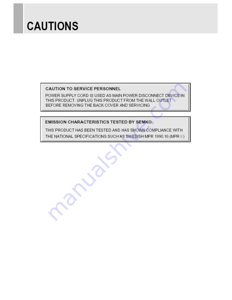
The power supply cord is used as the main disconnect device, ensure that the socket-outlet is 

located/installed near the equipment and is easily accessible. 

ATTENTION

Le cordon d`alimentation est utillsé comme interrupteur général. La prise de courant doit être 

située ou installée à proximité du matériel et être facile d`accès


 NEVER REMOVE THE BACK COVER 

Removal of the back cover should be carried out only by qualified personnel. 

 DO NOT USE IN HOSTILE ENVIRONMENTS 

To prevent shock or fire hazard, do not expose the unit to rain or moisture. 

This unit is designed to be used in the office or home. Do not subject the unit to vibrations, 

dust of corrosive gases. 

 KEEP IN A WELL VENTILATED PLACE 

Ventilation holes are provided on the cabinet to prevent the temperature from rising. 

Do not cover the unit or place anything on the top of unit. 

 AVOID HEAT 

Avoid placing the unit in direct sunshine or near a heating appliance. 

 TO ELIMINATE EYE FATIGUE 

Do not use the unit against a bright back ground and where sunlight or other light sources will 

shine directly on the monitor. 

 BE CAREFUL OF HEAVY OBJECT 

Neither the monitor itself nor any other heavy object should rest on the power cord. 

Damage to a power cord can cause fire or electrical shock. 


4   

……………………………………………………………………….    INSTRUCTION MANUAL


Summary of Contents for Premium Touch Screen CCTV Monitor

Page 1: ...32 INCH PREMIUM TOUCH SCREEN CCTV MONITOR INSTRUCTION MANUAL Please read this manual thoroughly before use and keep it handy for future reference ...

Page 2: ......

Page 3: ...NG WITH EXTERNAL EQUIPMENT 6 REMOTE FUNCTIONS 7 CONTROLS AND FUNCTIONS 8 44 MOUNTING GUIDE 45 D SUB CONNECTOR PIN ASSIGNMENTS 46 POWER MANAGEMENT 47 SPECIFICATIONS 48 49 TROUBLE SHOOTING GUIDE 50 INSTRUCTION MANUAL 1 This Monitor was Manufactured by ISO 9001 Certified Factory ...

Page 4: ...let consult an electrician for replacement of the bsolete outlet 10 Protect the power cord from being walked on or pinched particularly at plugs convenience receptacles and the point where they exit from the apparatus 11 Only use attachment accessories specified by the manufacturer 12 Use only with the cart stand tripod bracket or table specified by the manufacturer or sold with the apparatus When...

Page 5: ...pparatus shall not be exposed to dripping or splashing and no objects filled with liquids such as vases shall be placed on the apparatus This symbol is intended to alert the user to the presence of uninsulated dangerous voltage with in the product s enclosure that may be of sufficient magnitude to constitute a risk of electric shock to persons This symbol is intended to alert the user to the prese...

Page 6: ... rain or moisture This unit is designed to be used in the office or home Do not subject the unit to vibrations dust of corrosive gases KEEP IN A WELL VENTILATED PLACE Ventilation holes are provided on the cabinet to prevent the temperature from rising Do not cover the unit or place anything on the top of unit AVOID HEAT Avoid placing the unit in direct sunshine or near a heating appliance TO ELIMI...

Page 7: ...g the equipment off and on the user is encouraged to try to correct the interference by one or more of the following measures Reorient or relocate the receiving antenna Increase the separation between the equipment and receiver Connect the equipment into an outlet on a circuit different from that to which the receiver is connected Consult the dealer or an experienced radio TV technician for help O...

Page 8: ...2 IN 5 DVI IN 6 VGA D SUB IN 7 PC STEREO IN 8 AUDIO OUT Speaker 9 COMPONENT Y Pb Pr SOUND L R IN 10 TRIGGER INPUT B SIDE PANEL CONTROL 1 VIDEO1 AV1 IN 2 VIDEO1 AV1 OUT 3 VIDEO2 AV2 IN 4 VIDEO2 AV2 OUT 5 S VIDEO Y C IN 6 S VIDEO Y C OUT 7 VIDEO2 AV2 AUDIO IN 8 VIDEO2 AV2 AUDIO OUT 9 VIDEO1 AV1 S VIDEO AUDIO IN 10 VIDEO1 AV1 S VIDEO AUDIO OUT 6 INSTRUCTION MANUAL ...

Page 9: ...Displays the information about input source 12 STILL Pauses the picture 13 PIP Picture In Picture Activates the PIP mode 14 P INPUT Changes the source of sub picture in the PIP mode 15 P POS Changes the position of sub picture in the PIP mode 16 P SIZE Changes the sizes of sub and main pictures in the PIP mode 17 SWAP Alternates between sub and main pictures in the PIP mode 18 ARC Aspect Ratio Con...

Page 10: ... HOLD function and stop the Trigger Auto switching functions 5 6 VOL VOL Adjust the volume and menu settings 7 POWER ON OFF I Turns the power ON or OFF There will be a few seconds delay before the display appears 8 POWER LED The power LED lights with green when the power is turned ON The power is turned off by pressing the power switch again and the power LED goes Red 9 IR Sensor Remote controller...

Page 11: ...eft or right button to adjust the picture setting 4 Press the MENU button to save Brightness Increase or decrease the intensity of the image Contrast Increase or decrease the intensity lightness or dimness of the image Color Increase or decrease the colour of the picture Tint Increase or decrease the tint of the picture Sharpness Increase or decrease the sharpness of the picture INSTRUCTION MANUAL...

Page 12: ... the MENU button and then press the up or down button to select the Custom 2 Press the up or down button to select the sub menu 3 Press the left or right button to adjust the picture setting 4 Press the MENU button to save 10 INSTRUCTION MANUAL ...

Page 13: ...the up or down button to select the Picture Sound 2 Press the right or SOURCE button 3 Press the up or down button to select the Picture Mode 4 Press the right or SOURCE button 5 Press the up or down button to select the Picture Mode option 6 Press the MENU button to save INSTRUCTION MANUAL 11 ...

Page 14: ...or down button to select the Color Tone 2 Press the right or SOURCE button 3 Press the right or SOURCE button again 4 Press the up or down button to select the Color Tone option 5 Press the MENU button to save 12 INSTRUCTION MANUAL ...

Page 15: ... down button to select the User 2 Press the MENU button 3 Press the up or down button to select the User option 4 Press the left or right button to adjust the Red Green or Blue setting 5 Press the MENU button to save INSTRUCTION MANUAL 13 ...

Page 16: ...3 Mute 1 Press the up or down button to select the Mute 2 Press the right or SOURCE button 3 Press the up or down button to select the On or Off 4 Press the MENU button to save 14 INSTRUCTION MANUAL ...

Page 17: ...4 Volume 1 Press the up or down button to select the Volume 2 Press the left or right button to adjust Volume setting 3 Press the MENU button to save INSTRUCTION MANUAL 15 ...

Page 18: ...5 Size 1 Press the up or down button to select the Size 2 Press the right or SOURCE button 3 Press the up or down button to select the Size option 4 Press the MENU button to save 16 INSTRUCTION MANUAL ...

Page 19: ... Noise Reduction 1 Press the up or down button to select the NR 2 Press the right or SOURCE button 3 Press the up or down button to select the On or Off 4 Press the MENU button to save INSTRUCTION MANUAL 17 ...

Page 20: ... 3D Comb 1 Press the up or down button to select the 3D Comb 2 Press the right or SOURCE button 3 Press the up or down button to select the On or Off 4 Press the MENU button to save 18 INSTRUCTION MANUAL ...

Page 21: ...ture Sound Menu For RGB PC HDMI Input 1 Size 1 Press the up or down button to select the Size 2 Press the right or SOURCE button 3 Press the up or down button to select the Size option INSTRUCTION MANUAL 19 ...

Page 22: ... SOURCE button 5 Press the left or right button to adjust the PC setting 6 Press the MENU button to save Auto Adjust Auto geometry adjustment Phase Adjust the number of horizontal picture elements H Position Move image horizontally on screen right or left V Position Move image vertically on screen up or down Frequency Adjust the vertical noise of screen image 20 INSTRUCTION MANUAL ...

Page 23: ...ss the MENU button and then press the up or down button to select the PIP 1 PIP 1 Press the right or SOURCE button 2 Press up or down button to select the On or Off 3 Press the MENU button to save INSTRUCTION MANUAL 21 ...

Page 24: ...down button to select the Source option 4 Press the MENU button to save Possible PIP Combination Main Sub Video Video Video RGB PC or HDMI or DVI or Component RGB PC or HDMI or DVI or Component Video Impossible PIP Combination Main Sub RGB PC or HDMI or DVI or Component RGB PC or HDMI or DVI or Component 22 INSTRUCTION MANUAL ...

Page 25: ...wn button to select the PIP Mode 2 Press the right or SOURCE button 3 Press the up or down button to select the PIP Mode option 4 Press the MENU button to save PBP1 Main image Sub image PBP2 Main image Sub image INSTRUCTION MANUAL 23 ...

Page 26: ... PIP Size 1 Press the up or down button to select the Size 2 Press the right or SOURCE button 3 Press the up or down button to select the Size option 4 Press the MENU button to save 24 INSTRUCTION MANUAL ...

Page 27: ...n to select the Position 2 Press the right or SOURCE button 3 Press the up or down button to select the Position option 4 Press the MENU button to save RB Right of Bottom LB Left of Bottom LT Left of Top RT Right of Top INSTRUCTION MANUAL 25 ...

Page 28: ...6 Swap 1 Press the up or down button to select the Swap 2 Press the right or SOURCE button to swap the main image for the sub one 26 INSTRUCTION MANUAL ...

Page 29: ...ect 1 Press the up or down button to select the Sound Select 2 Press the right or SOURCE button 3 Press the up or down button to select the Sound Select option 4 Press the MENU button to save INSTRUCTION MANUAL 27 ...

Page 30: ...press the up or down button to select the Setup 1 Reset 1 Press the right or SOURCE button 2 Press the right or SOURCE button again 3 Press SOURCE button to execute the reset Reset All settings go to the factory initialization 28 INSTRUCTION MANUAL ...

Page 31: ...2 Language 1 Press the up or down button to select the Language 2 Press the right or SOURCE button 3 Press the up or down button to select language 4 Press the MENU button to save INSTRUCTION MANUAL 29 ...

Page 32: ... Tone 1 Press the up or down button to select the OSD Tone 2 Press the right or SOURCE button 3 Press the up or down button to select the OSD Tone option 4 Press the MENU button to save 30 INSTRUCTION MANUAL ...

Page 33: ...e Screen 1 Press the up or down button to select the Blue Screen 2 Press the right or SOURCE button 3 Press the up or down button to select the On or Off 4 Press the MENU button to save INSTRUCTION MANUAL 31 ...

Page 34: ...wn button to select the On or Off 4 Press the MENU button to save How to unlock 1 On the front key Press the MENU and button at the same time over 3 seconds 2 On the Remote Controller The Remote Controller operates well because the Key Lock function is only allowed for the front key of this product 32 INSTRUCTION MANUAL ...

Page 35: ...ger 2 Press the right or SOURCE button 6 1 Trigger Enable 1 Press the up or down button to select the Trigger Enable 2 Press the right or SOURCE button 3 Press the up or down button to select the On or Off 4 Press the Menu button to save INSTRUCTION MANUAL 33 ...

Page 36: ...put 1 Press the up or down button to select the Trigger Input 2 Press the right or SOURCE button 3 Press the up or down button to select the Trigger Input option 4 Press the Menu button to save 34 INSTRUCTION MANUAL ...

Page 37: ... 3 Buzzer 1 Press the up or down button to select the Buzzer 2 Press the right or SOURCE button 3 Press the up or down button to select the On or Off 4 Press the Menu button to save INSTRUCTION MANUAL 35 ...

Page 38: ...6 4 Trigger Time 1 Press the up or down button to select the Trigger Time 2 Press left or right button to adjust Trigger Time setting 3 Press the MENU button to save 36 INSTRUCTION MANUAL ...

Page 39: ...function is activated when the trigger cable is opened N O Normally Opened The Trigger function is activated when the trigger cable is closed High The Trigger function is activated when the trigger signal is DC 2 5 V Low The Trigger function is activated when the trigger signal is DC 0 0 6 V Note In this case trigger port has high status electrically so the trigger cable has to have ground or eart...

Page 40: ...ype option 4 Press the Menu button to save PIP FULL When the condition is below the Trigger Input image will be displayed as PIP Main Sub Video Video Video RGB PC or HDMI or DVI or Component RGB PC or HDMI or DVI or Component Video Otherwise it will be displayed as full screen FULL The Trigger Input image will be displayed as a full screen 38 INSTRUCTION MANUAL ...

Page 41: ... button to select the Auto Switching 2 Press the right or SOURCE button 7 1 Auto Switching On Off 1 Press the right or SOURCE button 3 Press the up or down button to select the On or Off 4 Press the Menu button to save INSTRUCTION MANUAL 39 ...

Page 42: ...ton to select the Inputs enable 2 Press the right or SOURCE button 3 Press the up or down button to select the Input 4 Press the right or SOURCE button 5 Press the up or down button to select the On or Off 6 Press the Menu button to save 40 INSTRUCTION MANUAL ...

Page 43: ...7 3 Auto Switching Time 1 Press the up or down button to select the Time 2 Press the left or right button to adjust the Time setting 3 Press the MENU button to save INSTRUCTION MANUAL 41 ...

Page 44: ... button to select the Image Rotation 2 Press the right or SOURCE button 8 1 Image Rotation On Off 1 Press the right or SOURCE button 3 Press the up or down button to select the On or Off 4 Press the Menu button to save 42 INSTRUCTION MANUAL ...

Page 45: ...8 2 Image Rotation Time 1 Press the up or down button to select the Time 2 Press the left or right button to adjust the Time setting 3 Press the MENU button to save INSTRUCTION MANUAL 43 ...

Page 46: ...0Hz Mode 1 Press the up or down button to select the 120Hz Mode 2 Press the right or SOURCE button 3 Press the up or down button to select the On or Off 4 Press the Menu button to save 44 INSTRUCTION MANUAL ...

Page 47: ...onitor is suitable for wall mounting by using the VESA 200 standard wall mount not included in the delivery Attention You must use four M6x8 screws to assemble this monitor and the wall mount bracket INSTRUCTION MANUAL 45 M6x8 screws ...

Page 48: ...ROUND 13 H SYNC or H V SYNC 6 RED GROUND 14 V SYNC 7 GREEN GROUND 15 SCL for DDC 8 BLUE GROUND D SUB ACCESSORIES 1 Power cord 2 User s manual 3 PC cable 4 Touch Screen Driver Installation CD 5 Trigger cable Option 6 Stereo cable Option 7 Remote controller Option 8 Batteries Option 9 Wall mount Option 46 INSTRUCTION MANUAL ...

Page 49: ...s of the signaling system POWER CONSUMPTION 120W LED INDICATOR The power management feature of the monitor is comprised of four stages On Green Standby Suspend Active off Red on off 1 sec and Unsupported mode Green MODE LED COLOR MONITOR OPERATION ON GREEN Normal Operation STANDBY RED ON OFF 1 SEC Screen blanks after preset idle time And some electronic circuits or all Circuitry in the monitor shu...

Page 50: ...n Y 1 5 or less Surface Hardness Mohs pick with hardness rating of 4 or higher Optical 88 2 550nm wavelength Reliability Rubber Stoke Operation Test load 250gf Press speed 2hits second Tip probe Sillicon rubber R8 0 Drop Test Touch panel is tested by 227g 38Ф steel ball Electrical Operating Voltage ESD DC 5 V DC 12V Contact 8KV Air 15KV Environment Temperature Humidity Test Relative Humidity Opera...

Page 51: ...EO 1ch input Y C loop through out COMPONENT Y Pb Pr Sound L R DVI Digital Video Interface HDMI1 HDMI2 High Definition Multimedia Interface PC RGB AV composite Sound In Out PC Stereo In TRIGGER In TOUCH PANEL USB Audio Out ACTIVE SCREEN SIZE 698 40 mm X 392 85 mm 27 50 X 15 47 PACKING DIMENSIONS W x H x D 875mm X 280mm X 635 mm 34 45 X 11 02 X 25 WEIGHT Net Weight 28 Kg 61 73 Ibs Gross Weight 31 Kg...

Page 52: ... the environment or human health from uncontrolled waste disposal please separate this from other types of wastes and recycle it responsibly to promote the sustainable reuse of material resources Household users should contact either the retailer where they purchased this product or their local government office for details of where and how they can take this item for environmentally safe recyclin...

Page 53: ...MEMO ...

Page 54: ...MEMO ...

Page 55: ...MEMO ...

Page 56: ...P N L39ME0246 Rev 2 ...

Reviews:

Related manuals for Premium Touch Screen CCTV Monitor