background image

6

Installation

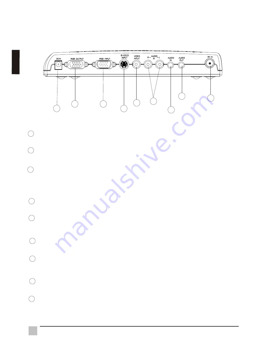
2.1.2 Rear view of 

VB50HRTV

1

2

3

4

5

6

7

8

9

RF IN (VHF/UHF)

Connect to antenna or cable TV signal.

AUDIO OUT

Connect the AUDIO OUT to your PC speakers.

AUDIO IN

Connect the audio cable from your sound card to the AUDIO IN port on the 

B50HRTV 

is not in use.

AUDIO (Left & Right) IN

Connect the external AUDIO IN to the 

VIDEO INPUT

Connect the external video from a VCR, Laser Disk, V8 or video game to the 
VIDEO INPUT port.

S-VIDEO INPUT

Connect the external S-video to the S-VIDEO INPUT port.

RGB INPUT

Using the 15-pin VGA cable provided, connect one side to the VGA output on 
your PC and the other side to the RGB INPUT of your VB50HRTV.

RGB OUTPUT

Connect your  15 pin monitor connector to the RGB output.

DC IN

Connect to a 12V power supply.

VB50HRTV. Your PC speakers will output an audio signal when the V

VB50HRTV. 

1

2

3

4

5

6

7

8

9

E

n

g

li

s

h


Summary of Contents for VB50HRTV

Page 1: ...VB50HRTV User Guide Guide de l utilisateur Manual de instucciones ...

Page 2: ... In the interest of continuing product improvement ViewSonic Corporation reserves the right to change product specifications without notice Information in this document may change without notice No part of this document may be copied reproduced or transmitted by any means for any purpose without prior written permission from ViewSonic Corporation Electronic Warranty Registration To meet your futur...

Page 3: ...am channels On Screen Display operation with IR remote controller MTS and SAP supported for NTSC system Important Notices Avoid exposure the to direct sunlight or high temperatures Avoid exposure the to moisture or high humidity Do not attempt repair yourself Your warranty dose not cover repair or attempted repair by anyone not authorized by Viewsonic If your VB50HRTV VB50HRTV VB50HRTV will not be...

Page 4: ... 2 3 Extend wiring 3 1 3 2 Remote 3 3 3 3 1 3 3 2 Troubleshooting Front view of Rear view of Initial Setting Control Advanced Setting MAIN MENU PICTURE setting 3 3 3 SOUND setting 3 3 4 OSD setting 3 3 5 PREFERENCE setting Including RESOLUTION and INPUT SIGNAL selection 3 3 6 CHANNEL setting Troubleshooting Appendix A Specifications Appendix B Limited Warranty Appendix C FCC Information 4 5 5 6 7 ...

Page 5: ...wing items If any items are missing contact your reseller VB50HRTV 1 VB50HRTV 2 Power supply 3 VGA cable 4 Audio cable 5 A V cable 7 Remote control 6 AAA batteries Chapter 1 Introduction 8 User manual English VB50HRTV User Guide Guide de l utilisateur Manual de instucciones ...

Page 6: ...O S VIDEO CABLE PC Press the INPUT button to switch the signals between C C TV or VIDEO S VIDEO CABLE TV or PC VOLUME Decreases the sound volume VOLUME Increases the sound volume CHANNEL Selects the next lower channel CHANNEL Selects the next higher channel Power indicator and IR infrared receiver Green LED indicates the status of power and IR receiver 1 2 3 4 5 6 7 1 2 3 4 5 6 7 English ...

Page 7: ... the VIDEO INPUT Connect the external video from a VCR Laser Disk V8 or video game to the VIDEO INPUT port S VIDEO INPUT Connect the external S video to the S VIDEO INPUT port RGB INPUT Using the 15 pin VGA cable provided connect one side to the VGA output on your PC and the other side to the RGB INPUT of your VB50HRTV RGB OUTPUT Connect your 15 pin monitor connector to the RGB output DC IN Connec...

Page 8: ...ectors or S Video connectors Disregard PC connections if you are only connecting your VB50HRTV to a monitor Speaker Cable Antenna RGB output from PC Monitor DVD VCR LD IRD Audio output from PC Camera Video game Adapter RCA A V cable S VIDEO cable WARNING Turn off all devices before you begin 7 Installation English Note Power indicator will flashing a short period when you plug the DC IN adapter Pr...

Page 9: ...ideo game RCA A V cable S VIDEO cable VCR Cable box DVD VCR LD IRD Speaker RGB output from PC Monitor Audio output from PC WARNING Turn off all devices before you begin Audio Video connection For audio connection use RCA audio L R connector For video connection use an RCA video connector or as S Video connector Disregard PC connections if you are only connecting your VB50HRTV to a monitor 8 Instal...

Page 10: ...amplifiers are available at your local electronics store Note Omit the splitter connection in the following figure if there is no cable modem present in your setup Two way splitter Cable modem Indoor Amp Cable or antenna outlet VGA output from PC PC The best location of an indoor amplifier is near a television 2 2 3 Extended wiring VCR Cable box AC outlet 9 Instruction English ...

Page 11: ...of Scan Scan program channels automatically and save scanned programs 0 9 Number Keys Used to select cable TV or VHF UHF program 2 3 4 5 6 7 8 9 10 Adjust the selected item on Menu or adjust the volume when Menu is not in use Press to select desired item on Menu or select channels up or down when Menu is not in use MTS Select MTS of MONO STEREO SAP 11 Res Select resolution of 1024x768 800x600 and ...

Page 12: ...RIGHTNESS CONTRAST SATURATION SHARPNESS HUE adjustment modes and RESET BRIGHTNESS CONTRAST SATURATION SHARPNESS PICTURE HUE 3 3 2 PICTURE settings To select BRIGHTNESS CONTRAST SATURATION SHARPNESS or HUE press or up down arrows To adjust selected item press or left right arrows Press Exit to return to the main menu Select RESET to return to factory settings 1 2 3 MAIN MENU PICTURE SOUND OSD PREFE...

Page 13: ... down arrows to select an item and press Select confirm setting and return to the Sub Menu Press Exit to return to the main menu Select RESET to return to factory settings SOUND Sub Menu provides VOLUME MTS TREBLE BASS adjustment modes and RESET 3 3 3 SOUND settings VOLUME MTS TREBLE RESET SOUND TREBLE BASS MONO STEREO EXIT SEL SAP MTS VOLUME MTS RESET SOUND TREBLE BASS EXIT SEL 1 2 3 4 English ...

Page 14: ...GUAGE press Select in OSD Using up down arrows to select the OSD language Press Exit to return to the main menu Select RESET to return to factory settings OSD POSITION EXIT SEL OSD Sub Menu provides OSD POSITION LANGUAGE selected mode and RESET 1 2 3 OSD POSITION RESET OSD EXIT SEL LANGUAGE OSD POSITION RESET OSD EXIT SEL LANGUAGE English ENGLISH EXIT SEL LANGUAGE ITALIANO DEUTSCH ESPANOL FRANCAIS...

Page 15: ...T mode press Select from the MODE menu Press or up down arrows to select an item then press Select to confirm and return to the Sub Menu PREFERENCE Sub Menu provides MODE RESOLUTION INPUT SIGNAL SLEEP and RESET select modes 3 3 5 PREFERENCE settings 1 2 INPUT SIGNAL EXIT SEL PREFERENCE TUNER INPUT RESOLUTION REFRESH MODE NORMAL SPORT MODE EXIT SEL CONTINUED ON NEXT PAGE 1024x768 800x600 RESOLUTION...

Page 16: ...T SIGNAL SEL EXIT CABLE TV PC To enter 60HZ or 75HZ of refresh rate press Select on the REFRESH menu Press or up down arrows to highlight an item then press Select to confirm and return to the Sub Menu 4 To enter C VIDEO S VIDEO CABLE TV or PC press Select button from the INPUT SIGNAL menu press or button to select an item Press Select to confirm and return to the Sub Menu 5 CONTINUED ON NEXT PAGE...

Page 17: ...m and press Select to confirm and return to the Sub Menu INPUT SIGNAL EXIT SEL PREFERENCE TUNER INPUT RESOLUTION REFRESH MODE ANTENNA CATV STD TUNER INPUT EXIT SEL CATV HRC CATV IRC 6 EXIT SEL PREFERENCE RESET SLEEP SLEEP EXIT SEL 45 MINS 60 MINS 15 MINS 30 MINS RESET EXIT SEL PREFERENCE RESET SLEEP To select ANTENNA CATV STD CATV HRC or CATV IRC press Select from the TUNER INPUT menu press or but...

Page 18: ...to access CH REMOVE Confirm CH REMOVE by pressing Select on your remote control To add a channel Use remote control to select the channel you want to add Enter the CHANNEL menu Use or up down arrows to access CH ADD Confirm CH ADD by pressing Select on your remote control Press Exit to return to the CHANNEL sub menu Press Exit again to return to the main menu CHANNEL provides AUTOSCAN CH ADD REMOV...

Page 19: ...arrows to highlight the selected column then press to pick a numeral or character Repeat the same procedure to input channel number and channel label 5 6 7 CH 26 REMOVE CH REMOVE AUTOSCAN CH ADD CHANNEL CHANNEL LABEL CH REMOVE EXIT SEL EXIT SEL AUTOSCAN CH REMOVE CHANNEL CHANNEL LABEL EXIT SEL CH LABEL EDITOR CH CH CH CH CH 0 2 6 EXIT SEL CH 026 CH LABEL EDITOR CH CH CH CH HBO EXIT SEL English ...

Page 20: ...ies are installed Check remaining battery life No sound Video is distorted Check the audio connection Make sure the speaker is working Press the Volume on remote control Check your antenna connections Try adjusting your antenna Check all of the connection Missing channels Some cable providers use scrambled or encoded signals that may require a cable box to view all available channels From TUNER IN...

Page 21: ...r NTSC VGA INPUT D Sub 15 pin Male connector VGA OUTPUT D Sub 15 pin Female connector Stereo L R RCA connectors PHONE IN Phone Jack 3 5 Operating Temperature 0 40 5 95 Operating Humidity Dimensions 231 50 L x 156 65 W x 36 80 H mm Weight 500g Remote Control 28 Buttons AAA batteries x2 S VIDEO INPUT S Video 4 pin mini DIN Power Consumption 15W nominal Appendix A English ...

Page 22: ... provide your product s serial number 2 To obtain service under warranty you will be required to provide a the original dated sales slip b your name c your address d a description of the problem and e the serial number of the prod uct 3 Take or ship the product freight prepaid in the original container to an authorized ViewSonic ser vice center or ViewSonic 4 For additional information or the name...

Page 23: ...tion which can be determined by turning the equipment off and on the user is encouraged to try to correct the interference by one or more of the following measures FCC Warning To assure continued FCC compliance the user must use grounded power supply cord and the provided shielded video interface cable with bonded ferrite cores If a BNC cable is going to be used use only a shielded BNC 5 cable Als...

Page 24: ...1 Espa ol ñ ...

Page 25: ...2 Espa o ñ l ...

Page 26: ...3 4 5 5 6 7 7 8 11 11 21 9 10 17 11 12 13 14 19 20 10 22 Espa ol ñ ...

Page 27: ...4 VB50HRTV User Guide Guide de l utilisateur Manual de instucciones Espa o ñ l ...

Page 28: ...5 1 2 3 4 5 6 7 1 2 3 4 5 6 7 Espa ol ñ ...

Page 29: ...6 1 2 3 4 5 6 7 8 9 1 2 3 4 5 6 7 8 9 5 Espa o ñ l ...

Page 30: ...Monitor 7 Espa ol ñ ...

Page 31: ...TV Altavoz Monitor 8 Espa o ñ l ...

Page 32: ...TV OUT 7dB OUT 7dB 12 16VDC 200mA INPUT 1GHz Drop Amplifier 5 40 54 1000MHz HDA R4 2 TAIWAN 9 Espa ol ñ ...

Page 33: ...10 1 2 3 4 5 6 7 8 9 10 11 12 13 14 Espa o ñ l ...

Page 34: ...11 1 2 3 Espa ol ñ ...

Page 35: ...12 TREBLE 1 2 3 4 Espa o ñ l ...

Page 36: ...13 1 2 3 Espa ol ñ ...

Page 37: ...14 1 2 SEL 3 Espa o ñ l ...

Page 38: ...15 4 5 Espa ol ñ ...

Page 39: ...16 CATV IRC 6 7 Espa o ñ l ...

Page 40: ...17 1 2 3 4 CONTINUA EN LA PÁGINA SIGUIENTE Espa ol ñ ...

Page 41: ...18 5 6 7 CH 26 REMOVE Espa o ñ l ...

Page 42: ...19 Espa ol ñ ...

Page 43: ...20 5 45 J J Espa o ñ l ...

Page 44: ...21 Espa ol ñ ...

Page 45: ......

Page 46: ......

Page 47: ...22 Espa o ñ l ...

Page 48: ...Corporation ...

Reviews: