background image

31

3.

Press 

/

 to select an adjustment method 

that suits your need and press 

Enter

.

4.

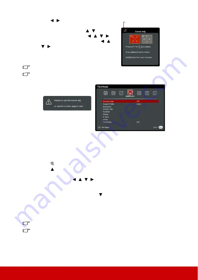
As indicated on the screen (

/

 for a 45-

degree angle adjustment and 

/

/

/

 for 

a 90-degree angle adjustment), press 

/

/

/

 to adjust its shape and size. You can 

press 

Menu

 or 

Exit

 to go back to a previous 

step. A long press for 2 seconds on 

Enter

 will 

reset the settings on the corner that you chose.

Adjusting keystone will reset the Corner Adj. settings.

After the Corner Adj. settings have been modified, some aspect ratios or timings are not 
available. When that happens, reset the settings on all 4 corners. 
The following messages will appear: 

Magnifying and searching for details

If you need to find the details on the projected picture, magnify the picture. Use the 

direction arrow keys for navigating the picture.

Using the remote control

1.

Press 

 on the remote control to display the Zoom bar.

2.

Press 

 repeatedly to magnify the picture to a desired size.

3.

To navigate the picture, press 

Enter

 to switch to the paning mode and press the 

directional arrows (

,

,

,

) to navigate the picture.

4.

To reduce size of the picture, you can press 

Auto Sync

 on the remote control to 

restore the picture to its original size. Or you can press 

Enter

 to switch back to the 

zoom in/out functionality and press 

.

Using the OSD menu

1.

Open the OSD menu and go to the 

DISPLAY > 

Zoom

 menu. 

2.

Press 

Enter

. The Zoom bar is displayed.

3.

Repeat steps 2-4 in the section of Using the remote control above.

This adjustable range may vary depending on different aspect ratios.

The picture can only be navigated after it is magnified. You can further magnify the picture 
while searching for details.

Indicates the corner that you 
selected.

Summary of Contents for Pro8510L

Page 1: ...stalling and using your product in a safe manner as well as registering your product for future service Warranty information contained in this User Guide will describe your limited coverage from ViewSonic Corporation which is also found on our web site at http box in the upper right corner of our website Antes de operar su equipo lea cu idadosamente las instrucciones en este manual ...

Page 2: ... correct the interference by one or more of the following measures y Reorient or relocate the receiving antenna y Increase the separation between the equipment and receiver y Connect the equipment into an outlet on a circuit different from that to which the receiver is connected y Consult the dealer or an experienced radio TV technician for help Warning by the party responsible for compliance coul...

Page 3: ...ong The wide blade and the third outlet consult an electrician for replacement of the obsolete outlet 10 Protect the power cord from being walked on or pinched particularly at plugs Convenience receptacles and the point where they exit from the unit Be sure that the power outlet is located near the unit so that it is easily accessible the manufacturer or sold with the unit When a cart is used use ...

Page 4: ... Certain components of products as stated above are exempted under the Annex III of the RoHS2 Directives as noted below Examples of exempted components are 1 J J lamps CCFL and EEFL for special purposes not exceeding per lamp 1 Short length 500 mm maximum 3 5 mg per lamp 2 Medium length 500 mm and 1 500 mm maximum 5 mg per lamp 3 Long length 1 500 mm maximum 13 mg per lamp 2 Lead in glass of catho...

Page 5: ...please visit your region section on ViewSonic s website to register your product online The ViewSonic CD also provides an opportunity for you to print the product registration form Upon completion please mail or fax to a respective ViewSonic office To find your registration form use the directory CD Registration Registering your product will best prepare you for future customer service needs Pleas...

Page 6: ...9 Magnifying and searching for details 31 Selecting the aspect ratio 32 Optimizing the image 33 Setting the presentation timer 36 Hiding the image 37 Locking control keys 38 Creating your own startup screen 38 Operating in a high altitude environment 38 Using the CEC function 39 Using the 3D functions 39 Controlling the projector through a LAN environment 40 Using the projector in standby mode 47 ...

Page 7: ... becomes extremely hot during operation Allow the projector to cool for approximately 45 minutes prior to removing the lamp assembly for replacement 8 Do not operate lamps beyond the rated lamp life Excessive operation of lamps beyond the rated life could cause them to break on rare occasions 9 Never replace the lamp assembly or any electronic components unless the projector is unplugged 10 Do not...

Page 8: ... is a normal phenomenon and not a product defect 20 Do not use the Security bar for transporting or installation It should be used with a commercially available theft prevention cable 21 CAUTION Possibly hazardous optical radiation emitted from this product Do not stare at operating lamp May be harmful to the eyes Risk Group 2 Warning THIS APPARATUS MUST BE EARTHED When installing the unit incorpo...

Page 9: ...est picture quality only for analog signal Digital keystone correction and 4 corner adjustment to correct distorted images Adjustable color management control for data video display Ability to display 1 07 billion colors Multi language On Screen Display OSD menus Switchable normal and economic modes to reduce the power consumption Component HDTV compatibility YPbPr HDMI CEC Consumer Electronics Co...

Page 10: ...Selects the desired menu items and makes adjustments Menu Turns on the On Screen Display OSD menu Exit Goes back to previous OSD menu exits and saves menu settings Enter Enacts the selected On Screen Display OSD menu item Displays the Corner Adj page Color Mode Selects an available picture setup mode Source Displays the source selection bar Help Displays the HELP menu by a long press for 3 seconds...

Page 11: ... VIDEO source for display Auto Sync Automatically determines the best picture timings for the displayed image Keystone keys Manually corrects distorted images resulting from an angled projection Enter Enacts the selected On Screen Display OSD menu item Displays the Corner Adj page Menu Turns on the On Screen Display OSD menu Left Right Up Down Selects the desired menu items and makes adjustments C...

Page 12: ...evel Presentation Timer Displays the presentation timer settings menu Eco Mode Selects a lamp mode Volume Down Decreases the volume level My Button Allows user to define a short cut key on the remote control and the function item is selected in OSD menu Source Displays the source selection bar Laser Emits visible laser pointer light for presentation purposes Exit Exits and saves menu settings PgUp...

Page 13: ...seconds or more The initial code is set to 1 When the code is switched to 8 the remote control can control every projector If different codes are set on the projector and remote control there will be no response from the remote control When that happens a message will display to remind you to switch the code for the remote control Using the remote mouse control The capability of operating your com...

Page 14: ...ow as illustrated 2 Remove any existing batteries if necessary and install two AAA batteries observing the battery polarities as indicated in the base of the battery compartment Positive goes to positive and negative goes to negative 3 Refit the cover by aligning it with the base and pushing it back down into position Stop when it clicks into place WARNING Avoid leaving the remote control and batt...

Page 15: ...t this location with the projector suspended upside down from the ceiling in front of the screen Purchase the projector ceiling mount kit from your dealer to mount your projector on the ceiling Set Front Ceiling in the SYSTEM Projector Position menu after you turn the projector on 3 Rear Ceiling Select this location with the projector suspended upside down from the ceiling behind the screen Note t...

Page 16: ... 4 3 image on a 16 10 screen a d c b e f a Screen Size inch cm 4 3 image on a 4 3 Screen b Projection distance m inch c Image height cm inch d Vertical offset cm inch min max min max 60 152 1 7 67 2 7 107 91 36 6 9 2 7 13 7 5 4 70 178 2 0 78 3 2 124 107 42 8 0 3 2 16 0 6 3 80 203 2 3 89 3 6 142 122 48 9 1 3 6 18 3 7 2 90 229 2 5 100 4 1 160 137 54 10 3 4 1 20 6 8 1 100 254 2 58 111 4 5 178 152 60 ...

Page 17: ...26 108 42 8 1 3 2 16 2 6 4 90 229 2 2 88 3 6 141 121 48 9 1 3 6 18 2 7 2 100 254 2 5 98 4 0 157 135 53 10 1 4 0 20 2 7 9 110 279 2 7 108 4 4 173 148 58 11 1 4 4 22 2 8 7 120 305 3 0 118 4 8 188 162 64 12 1 4 8 24 2 9 5 130 330 3 2 128 5 2 204 175 69 13 1 5 2 26 3 10 3 140 356 3 5 137 5 6 220 188 74 14 1 5 6 28 3 11 1 150 381 3 7 147 6 0 235 202 79 15 1 6 0 30 3 11 9 a c b e f d a c b e f d a c b e...

Page 18: ... 4 8 130 330 3 1 124 5 0 198 175 69 8 8 3 4 13 1 5 2 140 356 3 4 133 5 4 213 188 74 9 4 3 7 14 1 5 6 150 381 3 6 143 5 8 228 202 79 10 1 4 0 15 1 6 0 a Screen Size inch cm 16 10 image on a 4 3 Screen b Projection distance m inch c Image height cm inch d Vertical offset cm inch min max min max 60 152 1 4 54 2 2 86 76 30 3 8 1 5 5 7 2 3 70 178 1 6 63 2 6 100 89 35 4 4 1 8 6 7 2 6 80 203 1 8 72 2 9 1...

Page 19: ...5 7 5 2 9 130 330 3 0 118 4 8 188 162 64 4 0 1 6 8 1 3 2 140 356 3 2 127 5 1 203 174 69 4 4 1 7 8 7 3 4 150 381 3 4 136 5 5 217 187 74 4 7 1 8 9 3 3 7 a Screen Size inch cm 16 10 image on a 4 3 Screen b Projection distance m inch c Image height cm inch d Vertical offset cm inch min max min max 60 152 1 3 51 2 1 82 76 30 1 9 0 8 3 8 1 5 70 178 1 5 60 2 4 96 89 35 2 2 0 9 4 4 1 8 80 203 1 7 68 2 8 1...

Page 20: ...nch c Image height cm inch d Vertical offset cm inch min max min max 60 152 1 4 56 2 3 90 75 29 5 6 2 2 11 2 4 4 70 178 1 7 65 2 7 104 87 34 6 5 2 6 13 1 5 1 80 203 1 9 75 3 0 119 100 39 7 5 2 9 14 9 5 9 90 229 2 1 84 3 4 134 112 44 8 4 3 3 16 8 6 6 100 254 2 4 93 3 8 149 125 49 9 3 3 7 18 7 7 4 110 279 2 6 103 4 2 164 137 54 10 3 4 0 20 5 8 1 120 305 2 8 112 4 5 179 149 59 11 2 4 4 22 4 8 8 130 3...

Page 21: ...ift the projection lens upwards or downwards within the allowable range depending on your desired image position To use the lens shift wheel Turn the wheel to adjust the projected image position Do not over tighten the wheel Lens shift adjustment does not result in a degraded picture quality a Screen Size inch cm 16 9 image on a 4 3 Screen b Projection distance m inch c Image height cm inch d Vert...

Page 22: ... from electronics stores The connection illustrations below are for reference only The connecting jacks available on the projector vary with each projector model For detailed connection methods see pages 19 21 Below is the connection method for each connector that you may find on your projector HDMI connector A V device or Computer HDMI cable LAN connector RJ45 cable Internet Mini USB socket USB c...

Page 23: ...uency of 38KHz is supported Audio in Audio cable Computer Audio cable A V device or Computer Out VGA cable Monitor or VGA to DVI A cable S Video connector S Video cable A V device Video connector Video cable A V device Audio in L R Audio cable A V device USB 5V 2A Out USB Power Charger HDMI MHL connector HDMI dongle MHL dongle MicroUSB cable or IR Out Remote control wire ...

Page 24: ...a monitor symbol on the notebook Press FN and the labeled function key simultaneously Refer to your notebook s documentation to find your notebook s key combination Connecting a monitor If you want to view your presentation close up on a monitor as well as on the screen you can connect the COMPUTER OUT signal output socket on the projector to an external monitor with a VGA cable following the inst...

Page 25: ...nal is Component video not to be confused with composite video Digital TV tuner and DVD players output Component video natively so if available on your devices this should be your connection method of choice in preference to composite video See Connecting a Component Video source device on page 21 for how to connect the projector to a component video device Better video quality The S Video method ...

Page 26: ...TER IN 2 socket on the projector If the selected video image is not displayed after the projector is turned on and the correct video source has been selected check that the Video source device is turned on and operating correctly Also check that the signal cables have been connected correctly Connecting an S Video source device Examine your Video source device to determine if it has an unused S Vi...

Page 27: ...when the BASIC Audio Settings Audio In 2 menu is set to Microphone See Adjusting the Audio In 2 setting on page 48 for details Once connected the audio can be controlled by the projector On Screen Display OSD menus See Adjusting the sound on page 47 for details About the microphone input If you wish to use a microphone connect a 3 5 mini jack cable microphone to the projector You can use a wireles...

Page 28: ...nt cover helps you to conceal and organize the cables connected to the back of the projector It is especially useful when the projector is ceiling mounted or wall mounted 1 Make sure that all the cables are properly connected to the projector 2 Attach the cable management cover to the back of the projector 3 Tighten the screws that secure the cable management cover ...

Page 29: ...r On Off Ring Tone on page 48 for details 4 If the projector is activated for the first time select your OSD language following the on screen instructions 5 Switch all of the connected equipment on 6 The projector will start to search for input signals The current input signal being scanned appears in the upper left corner of the screen If the projector doesn t detect a valid signal the message No...

Page 30: ...u To use the OSD menus please select your language first 1 Press Menu to turn the OSD menu on 3 Press to highlight Language and press Enter 2 Use to highlight the SYSTEM menu 4 Use to select a preferred language 5 Press Menu twice to leave and save the settings The first press leads you back to the main menu and the second press closes the OSD menu Current input signal Main menu icon Sub menu High...

Page 31: ... 4 As pictured to the right the four arrow keys respectively represent 4 digits 1 2 3 4 According to the password you desire to set press the arrow keys to enter six digits for the password 5 Confirm the new password by re entering the new password Once the password is set the OSD menu returns to the Security Settings page 6 To leave the OSD menu press Exit If you forget the password If the passwo...

Page 32: ...4 Enter a new password 5 Confirm the new password by re entering the new password 6 You have successfully assigned a new password to the projector Remember to enter the new password next time the projector is started 7 To leave the OSD menu press Exit The digits being input will be displayed as asterisks on screen Do make a note of your password and then keep the note in a safe place for later rec...

Page 33: ...ome image distortion or loss of picture clarity See Selecting the aspect ratio on page 32 for details Changing HDMI input settings In the unlikely event that you connect the projector to a device like a DVD or Blu ray player via the projector s HDMI input and the projected picture displays wrong colors please change the color space to an appropriate one that fits the color space setting of the out...

Page 34: ...ns while the lamp is on The strong light from the lamp may cause damage to your eyes Auto adjusting the image In some cases you may need to optimize the picture quality To do this press Auto Sync on the remote control Within 5 seconds the built in Intelligent Auto Adjustment function will re adjust the values of Frequency and Clock to provide the best picture quality The current source information...

Page 35: ...rrect keystoning at the top of the image or press to correct keystoning at the bottom of the image Press to correct keystoning at the right side of the image Press to correct keystoning at the left side of the image The projector can automatically correct vertical keystone To do this open the OSD menu and go to the DISPLAY Keystone Auto V Keystone and press to select On Adjusting 4 corners You can...

Page 36: ...e direction arrow keys for navigating the picture Using the remote control 1 Press on the remote control to display the Zoom bar 2 Press repeatedly to magnify the picture to a desired size 3 To navigate the picture press Enter to switch to the paning mode and press the directional arrows to navigate the picture 4 To reduce size of the picture you can press Auto Sync on the remote control to restor...

Page 37: ...m without aspect alteration 3 16 9 Scales an image so that it is displayed in the center of the screen with a 16 9 aspect ratio This is most suitable for images which are already in a 16 9 aspect like high definition TV as it displays them without aspect alteration 4 16 10 Scales an image so that it is displayed in the center of the screen with a 16 10 aspect ratio This is most suitable for images...

Page 38: ...or environments where extra high brightness is required such as using the projector in well lit rooms 2 Dynamic mode Is designed for presentations under daylight environment to match PC and notebook coloring In addition the projector will optimize the image quality using the dynamic PC function in accordance with the projected contents 3 Standard mode Is designed for presentations under daylight e...

Page 39: ...ccording to the detected signal type there are some user definable functions available You can make adjustments to these functions based on your needs Adjusting Brightness Go to the IMAGE Brightness menu and press Enter The higher the value the brighter the image And the lower the setting the darker the image Adjust this control so the black areas of the image appear just as black and that detail ...

Page 40: ...her the setting the less the noise This function is only available when a PC Video or S Video input signal is selected Selecting a gamma setting Go to the IMAGE Advanced Gamma menu and select a preferred setting by pressing Gamma refers to the relationship between input source and picture brightness Selecting a Color Temperature Go to the IMAGE Color Temp menu and press Enter The options available...

Page 41: ...ts range at 0 only pure red in the projected picture will be selected Increasing its range will include red close to yellow and red close to magenta 5 Press to highlight Saturation and adjust its values to your preference by pressing Every adjustment made will reflect to the image immediately For example if you select Red and set its value at 0 only the saturation of pure red will be affected Satu...

Page 42: ...p 8 To activate the presentation timer press and press to highlight Start Counting and press Enter 9 A confirmation message displays Highlight Yes and press Enter to confirm You will see the message Timer is On displaying on the screen The timer starts counting when the timer is on To cancel the timer perform the following steps 1 Press on the remote control or go to the BASIC Presentation Timer m...

Page 43: ...turn off the projector without disabling panel key lock the projector will still be in locked status the next time it is turned on Creating your own startup screen In addition to selecting the projector preset startup screen from among Black Blue or ViewSonic screen you can make your own startup screen that is a picture projected from your computer or video source To create your own startup screen...

Page 44: ...connected to the HDMI input of the projector when the projector s power is turned off the power of the connected device will also be turned off automatically When the power of the connected device is turned on the projector s power will be turned on automatically To turn on the CEC function 1 Open the OSD menu and go to the POWER MANAGEMENT Auto Power On CEC menu 2 Press to select Enable In order ...

Page 45: ...the other end to the RJ45 port 2 Open the OSD menu and go to the ADVANCED LAN Control Settings menu 3 Press Enter The LAN Control Settings page is displayed 4 Highlight LAN Control Settings and press to select DHCP ON 5 Press to highlight Apply and press Enter 6 Please wait for around 15 20 seconds and then re enter the LAN Control Settings page The Projector IP Address Subnet Mask Default Gateway...

Page 46: ...lected Static IP and obtained the Projector IP Address Subnet Mask Default Gateway and DNS Server information when the projector is on Controlling the projector through a web browser Once you have the correct IP address for the projector and the projector is on or in standby mode you can use any computer that is on the same local area network to control the projector If you are using Microsoft Int...

Page 47: ...te at http www amx com 4 If your projector is connected to a network which supports Simple Mail Transfer Protocol SMTP you can configure it to alert you via email on significant events 5 The Crestron e Control page displays the Crestron e Control user interface See About Crestron e Control on page 44 for details ...

Page 48: ...X XXX XXX XXX Subnet Mask XXX XXX XXX XXX Gateway XXX XXX XXX XXX DNS Server XXX XXX XXX XXX AMX device discovery N A Password Administrator N A New Password 4 Confirm Password 4 SNMP SysLocation 22 SysName 22 SysContact 22 Email Alert Email Setting To 40 Cc 40 Subject 40 From 40 SMTP Setting Server 30 User Name 21 Password 14 Alert Condition Fan Error N A Lamp Error N A Over Temperature N A Lamp ...

Page 49: ...ries according to the connectors available on the projector When you use the projector control panel or remote control to change the OSD menu settings it may take a while for the web browser to synchronize these changes with the projector 2 The tools page allows you to manage the projector configure the LAN control settings and secure access of remote network operation on this projector i This sec...

Page 50: ...ved for the projector vi Press Exit to go back to the remote network operation page Please pay attention to the limitation of input length including space and other punctuation keys in the list blow Category Item Input Length Maximum Number of Characters Crestron Control IP Address 16 IP ID 4 Port 5 Projector Projector Name 32 Location 32 Assigned To 32 Network Configuration DHCP Enabled N A IP Ad...

Page 51: ...ation visit http www crestron com www crestron com getroomview Crestron RoomView On the Edit Room page enter the IP Address or hostname as shown on the projector s on screen display OSD menu and 02 for IPID 41794 for the reserved Crestron control port About Crestron RoomView setting and command method please access below website to get RoomView User Guide and more information http www crestron com...

Page 52: ...electing On in the ADVANCED LAN Control Settings Standby LAN Control allows the projector to provide the network function when it is in standby mode See Controlling the projector through a LAN environment on page 40 for details Adjusting the sound The sound adjustments made as below will have an effect on the projector speaker Be sure you have made a correct connection to the projector audio input...

Page 53: ...nd level This function is only available when the BASIC Audio Settings Audio In 2 menu is set to Microphone The microphone volume will be changed to 1 after each setting adjustment Turning off the Power On Off Ring Tone 1 Open the OSD menu and go to the BASIC Audio Settings Power On Off Ring Tone menu 2 Press to select Off The only way to change Power On Off Ring Tone is setting On or Off here Set...

Page 54: ...shes a Power Off Ring Tone will be heard Disconnect the power cord from the wall socket if the projector will not be used in an extended period of time To turn off the ring tone see Turning off the Power On Off Ring Tone on page 48 for details CAUTION To protect the lamp the projector will not respond to any commands during the cooling process Do not unplug the power cord before the projector shut...

Page 55: ...rd Whiteboard Aspect Ratio Auto 4 3 16 9 16 10 Panorama 2 35 1 Anamorphic Keystone Auto V Keystone Off On Manual Vertical Horizontal Corner Adj Position Phase H Size Zoom OverScan Off 1 2 3 4 5 2 IMAGE Color Mode Brightest Dynamic Standard ViewMatch sRGB Movie DICOM SIM Brightness Contrast Color Temp Warm Red Gain Green Gain Blue Gain Red Offset Green Offset Blue Offset Normal Neutral Cool Advance...

Page 56: ...ff On 4 BASIC Audio Settings Audio Mode Standard Speech Entertainment Mute On Off Audio Volume Audio In 2 Audio Microphone Microphone Volume Power On Off Ring Tone On Off Presentation Timer Timer Period 1 240 m Timer Display Always 1 min 2 min 3 min Timer Position Top Left Bottom Left Top Right Bottom Right Timer Counting Direction Count Down Count Up Sound Reminder On Off Start Counting Off Patte...

Page 57: ...o Off Frame Sequential Frame Packing Top Bottom Side by Side 3D Sync Invert Disable Invert HDMI Settings HDMI Format Auto RGB YUV HDMI Range Auto Enhanced Normal LAN Control Settings LAN Control Settings DHCP ON Static IP Projector IP Address Subnet Mask Default Gateway DNS Server Standby LAN Control Off On Apply Lamp Settings Lamp Mode Normal Eco Reset Lamp Hours Lamp Hours Filter Settings Filter...

Page 58: ...y Time 5 sec 10 sec 15 sec 20 sec 25 sec 30 sec Menu Position Center Top Left Top Right Bottom Left Bottom Right High Altitude Mode On Off Quick Auto Search Off On Security Settings Change Password Power On Lock Off On Panel Key Lock Off On Remote Control Code 1 2 3 4 5 6 7 8 7 INFORMATION Source Color Mode Resolution Color System IP Address MAC Address Firmware Version ...

Page 59: ...th every key press you made until they reach their maximum or minimum This function is only available when a PC input signal is selected The adjustment range may vary under different timings Phase Adjusts the clock phase to reduce image distortion This function is only available when a PC input signal is selected H Size Adjusts the horizontal width of the image This function is only available when...

Page 60: ...r details Advanced Color See Adjusting Color on page 34 for details Tint See Adjusting Tint on page 34 for details Sharpness See Adjusting Sharpness on page 35 for details Gamma See Selecting a gamma setting on page 35 for details Brilliant Color See Adjusting Brilliant Color on page 35 for details Noise Reduction See Reducing image noise on page 35 for details Color Management See Color Managemen...

Page 61: ...the HDMI MHL port can t be detected please do MHL Reset or switch power out MHL Reset Selecting Reset to reapply power after a power outage Audio Settings See Adjusting the sound on page 47 for details Presentation Timer See Setting the presentation timer on page 36 for details Pattern The projector can display several test patterns It helps you adjust the image size and focus and check that the p...

Page 62: ...es according to the input image detected This function is only available when a PC input signal is selected After enabling DCR frequent lamp mode switching may shorten lamp life and noise level will vary during operation Closed Caption Selects a preferred closed captioning mode when the selected input signal carries closed captions Captions An on screen display of the dialogue narration and sound ...

Page 63: ...witching input signal on page 28 for details Security Settings See Utilizing the password function on page 26 for details Panel Key Lock See Locking control keys on page 38 for details Remote Control Code See Remote control code on page 8 for details Current System Status Source Shows the current signal source Color Mode Shows the selected mode in the IMAGE menu Resolution Shows the native resolut...

Page 64: ...ve stubborn dirt or stains moisten a soft cloth with water and a neutral pH detergent Then wipe the case CAUTION Never use wax alcohol benzene thinner or other chemical detergents These can damage the case Storing the projector If you need to store the projector for an extended time please follow the instructions below Make sure the temperature and humidity of the storage area are within the recom...

Page 65: ...tion 1 Open the OSD menu and go to the ADVANCED Filter Settings menu 2 Press Enter The Filter Settings page is displayed 3 You will see the Filter Hours information on the menu Cleaning the dust filter 1 Be sure to turn off the projector and unplug it from power source 2 Remove the screws that secure the dust filter cover 3 Remove the filter from the projector 4 Use a small vacuum cleaner or a sof...

Page 66: ...remote control to select Setting Auto Power Off This function allows the projector to turn off automatically after a set period of time once no input source is detected to prevent unnecessary waste of lamp life 1 Open the OSD menu and go to the POWER MANAGEMENT Smart Energy menu 2 Press Enter and the Smart Energy page is displayed 3 Highlight Auto Power Off and press 4 If the preset time lengths a...

Page 67: ...up An old lamp may cause a malfunction in the projector and in some instances the lamp may explode CAUTION The Lamp indicator light and Temperature indicator light will light up if the lamp becomes too hot Turn the power off and let the projector cool for 45 minutes If the Lamp indicator light or Temperature indicator light still lights up after turning the power back on please contact your dealer...

Page 68: ...ctual fan speed is 25 outside the desired speed Off Red Blue Fan 3 error the actual fan speed is 25 outside the desired speed Off Red Purple Fan 4 error the actual fan speed is 25 outside the desired speed Red Red Red Thermal sensor 1 open error the remote diode has an open circuit condition Red Red Blue Thermal sensor 2 open error the remote diode has an open circuit condition Blue Red Red Therma...

Page 69: ... connected to the input signal device Check the connection The input signal has not been correctly selected Select the correct input signal with the Source key on the projector or remote control Cause Remedy The projection lens is not correctly focused Adjust the focus of the lens using the focus ring The projector and the screen are not aligned properly Adjust the projection angle and direction a...

Page 70: ...ons Dimensions 469 5 mm W x 139 8 mm H x 316 24 mm D Including extrusions Ceiling mount installation ZOOM FOCUS 469 5 139 8 316 24 164 10 291 20 286 20 3 50 8 16 133 10 Ceiling mount screws M4 x 8 Max L 8 mm Unit mm ...

Page 71: ...ON NEC X3 F4 17 E8 Presentation Timer NEC X3 F4 27 D8 Exit NEC X3 F4 28 D7 Eco Mode NEC X3 F4 2B D4 Menu NEC X3 F4 30 CF Mouse NEC X3 F4 31 CE Mouse Left NEC X3 F4 36 C9 Mouse Right NEC X3 F4 37 C8 Source NEC X3 F4 40 BF Pattern NEC X3 F4 55 AA My button NEC X3 F4 56 A9 HDMI NEC X3 F4 58 A7 Volume NEC X3 F4 82 7D Volume NEC X3 F4 83 7C Magnify NEC X3 F4 18 e7 Aspect NEC 83 F4 13 EC Video NEC 83 F4...

Page 72: ... 83F4 Code 2 93F4 Code 3 A3F4 Code 4 B3F4 Code 5 C3F4 Code 6 D3F4 Code 7 E3F4 Code 8 F3F4 Pin Description Pin Description 1 NC 2 RX 3 TX 4 NC 5 GND 6 NC 7 RTSZ 8 CTSZ 9 NC RS 232 protocol Baud Rate 115200 bps default Data Length 8 bit Parity Check None Stop Bit 1 bit Flow Control None ...

Page 73: ...00 0x04 0x00 0x34 0x11 0x0A 0x03 0x6A Splash Screen Off 0x06 0x14 0x00 0x04 0x00 0x34 0x11 0x0A 0x04 0x6B Read Splash Screen status 0x07 0x14 0x00 0x05 0x00 0x34 0x00 0x00 0x11 0x0A 0x68 Quick Power Off Write Quick Power Off Off 0x06 0x14 0x00 0x04 0x00 0x34 0x11 0x0B 0x00 0x68 Quick Power Off On 0x06 0x14 0x00 0x04 0x00 0x34 0x11 0x0B 0x01 0x69 Read Quick Power Off status 0x07 0x14 0x00 0x05 0x00...

Page 74: ... 0x12 0x20 0x02 0x80 Frame Packing 0x06 0x14 0x00 0x04 0x00 0x34 0x12 0x20 0x03 0x81 Top Bottom 0x06 0x14 0x00 0x04 0x00 0x34 0x12 0x20 0x04 0x82 Side by Side 0x06 0x14 0x00 0x04 0x00 0x34 0x12 0x20 0x05 0x83 Read 3D Sync Status 0x07 0x14 0x00 0x05 0x00 0x34 0x00 0x00 0x12 0x20 0x7F 3D Sync Invert Write Off 0x06 0x14 0x00 0x04 0x00 0x34 0x12 0x21 0x00 0x7F On 0x06 0x14 0x00 0x04 0x00 0x34 0x12 0x2...

Page 75: ...tion shift right 0x06 0x14 0x00 0x04 0x00 0x34 0x12 0x06 0x01 0x65 Horizontal position shift left 0x06 0x14 0x00 0x04 0x00 0x34 0x12 0x06 0x00 0x64 Read Horizontal position 0x07 0x14 0x00 0x05 0x00 0x34 0x00 0x00 0x12 0x06 0x65 Vertical position Write Vertical position shift up 0x06 0x14 0x00 0x04 0x00 0x34 0x12 0x07 0x00 0x65 Vertical position shift down 0x06 0x14 0x00 0x04 0x00 0x34 0x12 0x07 0x...

Page 76: ...0x00 0x04 0x00 0x34 0x12 0x0B 0x04 0x6D ViewMatch sRGB 0x06 0x14 0x00 0x04 0x00 0x34 0x12 0x0B 0x05 0x6E Dynamic 0x06 0x14 0x00 0x04 0x00 0x34 0x12 0x0B 0x08 0x71 DICOM SIM 0x06 0x14 0x00 0x04 0x00 0x34 0x12 0x0B 0x0a 0x73 Read Preset mode status 0x07 0x14 0x00 0x05 0x00 0x34 0x00 0x00 0x12 0x0B 0x6A Primary Color Write Primary color R 0x06 0x14 0x00 0x04 0x00 0x34 0x12 0x10 0x00 0x6E Primary colo...

Page 77: ...0 0x04 0x00 0x34 0x13 0x01 0x08 0x68 Input source HDMI 1 0x06 0x14 0x00 0x04 0x00 0x34 0x13 0x01 0x03 0x63 Input source HDMI 2 0x06 0x14 0x00 0x04 0x00 0x34 0x13 0x01 0x07 0x67 Input source HDMI 3 0x06 0x14 0x00 0x04 0x00 0x34 0x13 0x01 0x09 0x69 Input source HDMI MHL 4 0x06 0x14 0x00 0x04 0x00 0x34 0x13 0x01 0x0e 0x6e Input source Video 0x06 0x14 0x00 0x04 0x00 0x34 0x13 0x01 0x05 0x65 Input sour...

Page 78: ... 0x34 0x15 0x00 0x07 0x68 0x06 0x14 0x00 0x04 0x00 0x34 0x15 0x00 0x08 0x69 0x06 0x14 0x00 0x04 0x00 0x34 0x15 0x00 0x09 0x6A 0x06 0x14 0x00 0x04 0x00 0x34 0x15 0x00 0x0a 0x6B 0x06 0x14 0x00 0x04 0x00 0x34 0x15 0x00 0x0b 0x6C 0x06 0x14 0x00 0x04 0x00 0x34 0x15 0x00 0x0c 0x6D 0x06 0x14 0x00 0x04 0x00 0x34 0x15 0x00 0x0d 0x6E 0x06 0x14 0x00 0x04 0x00 0x34 0x15 0x00 0x0e 0x6F 0x06 0x14 0x00 0x04 0x00...

Page 79: ...0 0x05 0x00 0x34 0x00 0x00 0x11 0x28 0x86 HDMI Range Write Enhanced 0x06 0x14 0x00 0x04 0x00 0x34 0x11 0x29 0x00 0x86 Normal 0x06 0x14 0x00 0x04 0x00 0x34 0x11 0x29 0x01 0x87 Auto 0x06 0x14 0x00 0x04 0x00 0x34 0x11 0x29 0x02 0x88 Read HDMI Range status 0x07 0x14 0x00 0x05 0x00 0x34 0x00 0x00 0x11 0x29 0x87 CEC Write Off 0x06 0x14 0x00 0x04 0x00 0x34 0x11 0x2B 0x00 0x88 On 0x06 0x14 0x00 0x04 0x00 ...

Page 80: ...0x34 0x12 0x0F 0x08 0x75 Brilliant Color 9 0x06 0x14 0x00 0x04 0x00 0x34 0x12 0x0F 0x09 0x76 Brilliant Color 10 0x06 0x14 0x00 0x04 0x00 0x34 0x12 0x0F 0x0A 0x77 Read Brilliant Color status 0x07 0x14 0x00 0x05 0x00 0x34 0x00 0x00 0x12 0x0F 0x6E Remote Control code Write code 1 0x06 0x14 0x00 0x04 0x00 0x34 0x0C 0x48 0x00 0xA0 code 2 0x06 0x14 0x00 0x04 0x00 0x34 0x0C 0x48 0x01 0xA1 code 3 0x06 0x1...

Page 81: ... 0x11 0x33 0x03 0x93 Overscan 4 0x06 0x14 0x00 0x04 0x00 0x34 0x11 0x33 0x04 0x94 Overscan 5 0x06 0x14 0x00 0x04 0x00 0x34 0x11 0x33 0x05 0x95 Read Overscan status 0x07 0x14 0x00 0x05 0x00 0x34 0x00 0x00 0x11 0x33 0x91 Remote Key Write Menu 0x02 0x14 0x00 0x04 0x00 0x34 0x02 0x04 0x0F 0x61 Exit 0x02 0x14 0x00 0x04 0x00 0x34 0x02 0x04 0x13 0x65 Top 0x02 0x14 0x00 0x04 0x00 0x34 0x02 0x04 0x0B 0x5D ...

Page 82: ...1280 x 768 15 9 60 1280 x 800 16 10 60 75 85 1360 x 768 16 9 60 Quad VGA 1280 x 960 4 3 60 85 SXGA 1280 x 1024 5 4 60 SXGA 1400 x 1050 4 3 60 WXGA 1440 x 900 16 10 60 UXGA 1600 x 1200 4 3 60 WSXGA 1680 x 1050 16 10 60 HD 1280 x 720 16 9 60 MAC 13 640 x 480 4 3 67 MAC 16 832 x 624 4 3 75 MAC 19 1024 x 768 4 3 75 MAC 21 1152 x 870 4 3 75 HDTV 1080p 1920 x 1080 16 9 60 WUXGA 1920 x 1200 16 10 60 ...

Page 83: ... 60 Quad VGA 1280 x 960 4 3 60 SXGA 1280 x 1024 5 4 60 SXGA 1400 x 1050 4 3 60 WXGA 1440 x 900 16 10 60 WSXGA 1680 x 1050 16 10 60 HDTV 1080p 1920 x 1080 16 9 50 60 HDTV 1080i 1920 x 1080 16 9 50 60 HDTV 720p 1280 x 720 16 9 50 60 SDTV 480p 720 x 480 4 3 16 9 60 SDTV 576p 720 x 576 4 3 16 9 50 SDTV 480i 720 x 480 4 3 16 9 60 SDTV 576i 720 x 576 4 3 16 9 50 WUXGA 1920 x 1200 16 10 60 ...

Page 84: ... Sequential formats 120 Hz signals are supported for Frame Sequential format only Video signal SDTV 480i is supported for Frame Sequential format only HDMI 3D In Frame packing format Signal Resolution dots Aspect Ratio Refresh Rate Hz 1080p 1920 x 1080 16 9 23 98 24 720p 1280 x 720 16 9 50 59 94 60 In Side by side format Signal Resolution dots Aspect Ratio Refresh Rate Hz 1080i 1920 x 1080 16 9 50...

Page 85: ...50 60 HDTV 1080i 1920 x 1080 16 9 50 60 HDTV 720p 1280 x 720 16 9 50 60 SDTV 480p 720 x 480 4 3 16 9 60 SDTV 576p 720 x 576 4 3 16 9 50 SDTV 480i 720 x 480 4 3 16 9 60 SDTV 576i 720 x 576 4 3 16 9 50 Composite video Signal Aspect Ratio Refresh Rate Hz NTSC 4 3 60 PAL 4 3 50 PAL60 4 3 60 SECAM 4 3 50 ...

Page 86: ...370 W RCL 103 Input connector RGB in 2 Component input shared with RGB in S Video 1 Composite input 1 Audio in 2 RCA R L 1 Microphone 1 share with audio in 2 Mini USB 1 HDMI 1 4a 3 HDMI MHL 1 dongle 3D VESA 1 Output connector RGB out 1 Audio out 1 Speaker 10 watt x 2 USB type A 5V 2A 1 USB microUSB Wire 5V 2A 1 Control terminal RS 232 serial control 9 pin x 1 LAN RJ45 x 1 12V Trigger 1 IR receiver...

Page 87: ...nmental Requirements Operating Temperature 0 C 40 C at sea level Operating Altitude 0 1499 m at 5 C 35 C 1500 3000 m at 5 C 25 C with High Altitude Mode on Operating Relative Humidity 10 90 without condensation ...

Page 88: ... Disclaimer ViewSonic Corporation makes no representations or warranties either expressed or implied with respect to the contents hereof and specifically disclaims any warranties merchantability or fitness for any particular purpose Further ViewSonic Corporation reserves the right to revise this publication and to make changes from time to time in the contents hereof without obligation to notify a...

Page 89: ...erica Columbia www viewsonic com la C http www viewsonic com la soporte servicio tecnico soporte viewsonic com Latin America Mexico www viewsonic com la C http www viewsonic com la soporte servicio tecnico soporte viewsonic com Nexus Hightech Solutions Cincinnati 40 Desp 1 Col De los Deportes Mexico D F Tel 55 6547 6454 55 6547 6484 Other places please refer to http www viewsonic com la soporte se...

Page 90: ...a projector s use includes more than fourteen 14 hours average daily usage North and South America One 1 year warranty for all parts excluding the lamp one 1 year for labor and ninety 90 days for the warranty for all parts excluding the lamp one 1 year for labor and ninety 90 days Other regions or countries Please check with your local dealer or local ViewSonic manufacturer s installed lamp only A...

Page 91: ...aused by any defects in the product damages based business opportunity loss of goodwill interference with business relationships or other commercial loss even if advised of the possibility of such damages 2 Any other damages whether incidental consequential or otherwise 3 Any claim against the customer by any other party Effect of local law which vary from local authority Some local governances do...

Page 92: ...roduct s serial number so please record the product information in the space provided below on your purchase for your future use Please retain your receipt of proof of purchase to support your warranty claim For Your Records Product Name ________________________ Model Number ____________________________ Document Number ____________________ Serial Number ____________________________ Purchase Date _...

Page 93: ... Tel 4136954 E Mail Cefeo soluglobales com Cuernavaca Compusupport de Cuernavaca SA de CV Francisco Leyva 178 Col Miguel Hidalgo C P 62040 Cuernavaca Morelos Tel 01 777 3180579 01 777 3124014 E Mail aquevedo compusupportcva com Distrito Federal QPLUS S A de C V Av Coyoacán 931 Col Del Valle 03100 México D F Tel 01 52 55 50 00 27 35 E Mail gacosta qplus com mx Guadalajara Jal SERVICRECE S A de C V ...

Page 94: ......

Reviews: