background image

16

ViewSonic  PJ751

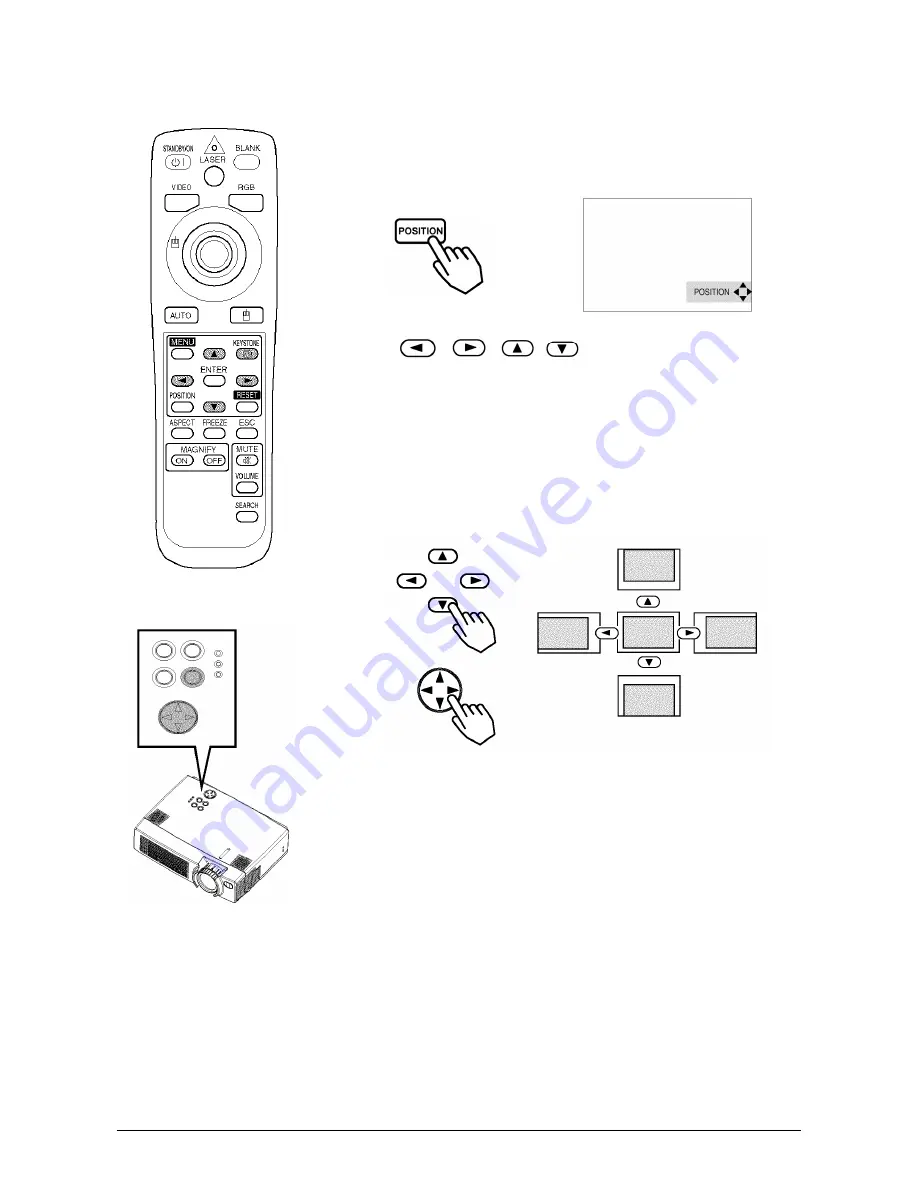
Adjusting the Image Position

1


Press the POSITION button

As illustrated on the right, a dialog box will appear on the screen to aid 

you in adjusting the position.

2


Use the 

buttons to adjust the position

When you want to initialize the position, press the RESET button dur-

ing adjustment.

Press the POSITION button again to close the dialog box and com-

plete this operation. (If no activity is detected, the dialog will automat-

ically disappear after a few seconds.)

This function is only available for RGB IN 1/2 input.

Control Panel

Summary of Contents for PJ751

Page 1: ...User Guide Guide de l utilisateur Bedlenungsanleltung Gu a del usuario Guida Dell utente Anv ndarhandbok K ytt opas PJ751 Image Size 31 300 LCD Projector...

Page 2: ...Selecting an Input Signal 14 Adjusting Image Size and Focus 14 Adjusting the Volume 15 Temporarily Muting the Sound 15 Adjusting the Image Position 16 Using the Automatic Adjustment Feature 17 Correct...

Page 3: ...net and Remote Control Transmitter 32 TROUBLESHOOTING On Screen Messages 33 Problem Diagnostics 34 SPECIFICATIONS Outline Dimensions 35 Customer Support 36 LIMITED WARRANTY ViewSonic Projector 37 Appe...

Page 4: ...onic Corporation shall not be lia ble for technical or editorial errors or omissions contained herein nor for incidental or consequential damages resulting from furnishing this material or the perform...

Page 5: ...for clear images in any settings 2 Whisper mode for quiet operation and extended lamp life 3 Magnification feature allows selected parts of the screen to be magnified for closer viewing 4 My Screen f...

Page 6: ...OTE Applicable power cord is shipped with the projector to the point of destination WARNING Before using this equipment read this manual thoroughly Always ensure that the equipment is used safely Powe...

Page 7: ...Terminal USB Terminal Foot Adjuster FRONT LEFT VIEW OF THE PROJECTOR REAR RIGHT VIEW OF THE PROJECTOR TERMINAL PANEL Speaker Handle Hook Power Switch AC Inlet to the Power Cord Ventilation Openings In...

Page 8: ...oling fan outlet Do not attempt to disassemble the remote control device VIDEO Button STANDBY ON Button Disk pad Used to operate the mouse shift function and left click function AUTO Button MENU Butto...

Page 9: ...o environmental pollution Before disposing of the batteries please be sure to observe the respective regulations concerning the protection of environment in your country or area Always be sure to keep...

Page 10: ...up and cause malfunctions or damage Never block the ventilation holes Do not install the projector in a smoky environment since smoke residue may accumulat on crit ical parts i e LCD panel lens etc An...

Page 11: ...ed with RGB IN 2 USB mouse control USB Optional USB cable PS 2 mouse control CONTROL Accessory PS 2 mouse cable ADB mouse control Optional ADB mouse cable Serial mouse control Optional serial mouse ca...

Page 12: ...CRT display or to simultaneous LCD and CRT display For more information refer to the instruction manual of the notebook computer Plug Play This projector is compatible with VESA DDC 1 2B Plug Play is...

Page 13: ...instruction manual of the corresponding laptop computer NOTE Some computers may have multiple display screen modes The use of some of these modes may not be possible with this projector For some RGB...

Page 14: ...AUDIO VIDEO IN AUDIO VIDEO OUT AUDIO VIDEO cable COMPONENT cable S VIDEO cable If using a S video connection If using a component video connection If using an audio video connection DVD player VCR S...

Page 15: ...12 ViewSonic PJ751 Connecting to a Display Monitor RGB OUT RGB IN RGB cable Display monitor...

Page 16: ...the STANDBY ON button again The projector lamp is turned off and the lamp will cool down The POWER indica tor blinks orange when the lamp cools down Pressing the STANDBY ON button has no effect while...

Page 17: ...t the signal you wish to project If selecting video input Press the VIDEO button Press this button to toggle between the devices connected to VIDEO IN SVIDEO IN and COMPONENT VIDEO As illustrated belo...

Page 18: ...on t do anything the dialog box will automatically disappear after a few seconds Temporarily Muting the Sound 1 Press the MUTE button As illustrated on the right a dialog will appear on the screen ind...

Page 19: ...osition 2 Use the buttons to adjust the position When you want to initialize the position press the RESET button dur ing adjustment Press the POSITION button again to close the dialog box and com plet...

Page 20: ...ndow is set to its maximum size prior to attempting to use this feature Dark pictures may still be incorrectly adjusted Use a bright screen when adjusting Automatic Adjustment for Video Input The inpu...

Page 21: ...irection of distortion to correct 3 Use the buttons to correct the distortion Press the KEYSTONE button again to close the dialog box and com plete this operation If no activity is detected the dialog...

Page 22: ...tomatically exit from MAGNIFY mode if either the INPUT SELECT AUTO ASPECT or VIDEO feature is used or if there is a change in the input signal s state Freezing the Screen 1 Press the FREEZE button The...

Page 23: ...r to the search Selecting the Aspect Ratio 1 Press the ASPECT button RGB IN 1 RGB IN 2 COMPONENT VIDEO HDTV signals 1125i 1035i 1080i 720p VIDEO IN S VIDEO IN COMPONENT VIDEO Non HDTV signals 525i 525...

Page 24: ...the buttons to select PIC TURE 1 then press the or ENTER button 3 Select an item using the buttons then press or the ENTER button The operation display of the selected item appears To adjust a numeric...

Page 25: ...control it may not be possible to control notebook PCs and other computers with built in pointing devices e g track balls In this case before connecting go into BIOS sys tem setup select external mou...

Page 26: ...each separate menu Initialization of settings and or adjustments During operation press the RESET button Note that items whose functions are performed simultaneously with the operation of clock phase...

Page 27: ...VIDEO S VIDEO COMPONENT VIDEO Dark Light TINT Adjust Tint for VIDEO S VIDEO Green Red Item Description V POSITION Adjust Vertical Position for RGB Up Down H POSITION Adjust Horizontal Position for RG...

Page 28: ...l refer to the item HDTV below VIDEO Select Mode of Signal Type for VIDEO S VIDEO AUTO NTSC PAL SECAM NTSC4 43 M PAL N PAL Selecting AUTO mode activates and performs the AUTO function for VIDEO SVIDEO...

Page 29: ...onfirmation using the actual screen s Option screens Various colored non patterned plain screens displayed within the Menus The MyScreen and the ORIGINAL Screen will each change to a non patterned pla...

Page 30: ...ayed When the Move the capture area as you want message has been displayed pressing the ESC or RESET button will eliminate the static state of the picture and operations can be performed again from op...

Page 31: ...being displayed The reset menu will then appear After you replace the lamp with a new lamp select RESET on the menu with the button Do not reset the lamp time unless you have replaced the lamp And al...

Page 32: ...s probable that the lamp has exploded you have heard an explosive sound disconnect the power plug from the power outlet and ask your dealer to replace the lamp The lamp is protected by a cover glass b...

Page 33: ...mage or injury Do not turn on with lamp cover removed Do not reset the lamp timer without replacing the lamp Always reset the lamp timer when the lamp is replaced 1 Switch the projector OFF remove the...

Page 34: ...wSonic Corp Replace the old filter then put the grill back in place 4 To reset the Filter Timer turn on the projector power go to the Option menu then select filter timer Reset the filter timer CAUTIO...

Page 35: ...f soiling is severe dip a soft cloth in water or a neutral cleanser diluted in water and wipe lightly after wringing well Then wipe lightly with a soft dry cloth CAUTION Make sure to turn off the powe...

Page 36: ...MER A note of precaution when cleaning the air filter After cleaning the filter operate FILTER TIME of the OPTION Menu then perform reset of the filter timer NO INPUT IS DETECTED ON There is no input...

Page 37: ...ly re connect the connection cord Pictures are displayed but no sounds are heard The electrical wiring to this unit is not correctly connected Correctly re connect the connection cord The volume setti...

Page 38: ...0 W stereo Power supply AC 100 120 V 3 3 A AC 220 240 V 1 4 A Power consumption 310 W typ Temperature range 0 35 C 32 95 F Operating Size 298 W x 76 H x 228 D mm 11 7 W x 3 73 H x 9 00 D inches Weight...

Page 39: ...onic com United Kingdom viewsoniceurope com T 0800 833 648 F 01293 643910 service eu viewsoniceurope com Europe Middle East Baltic countries and North Africa viewsoniceurope com Contact your reseller...

Page 40: ...pport You will need to provide your product s serial number To obtain warranted service you will be required to provide a the original dated sales slip b your name c your address d a description of th...

Page 41: ...ted to the terminal in the plug which is marked by the letter E or by the Earth symbol or coloured GREEN or GREEN AND YEL LOW The wire which is coloured BLUE must be connected to the terminal in the p...

Page 42: ...must use a cord set which is appropriate for the receptacles in your country The cord set is HAR Certified and a special mark that will appear on the outer sheath or on the insulation of one of the in...

Page 43: ...or an experienced radio TV technician for help FCC Warning To assure continued FCC compliance the user must use grounded power supply cord and the pro vided shielded video interface cable with bonded...

Page 44: ...ViewSonic Corporation...

Reviews: