


4
PJ650 (C3XM4)
5
PJ650
4-2 Ghost adjustment
Signals for internal adjustment
���
���
�������
�����
Adjustment procedure
1. Use DAC-P - GHOST - R: in the Adjustment menu
to adjust so that R color ghost is at a minimum.
(Set the adjustment value to default, and then
raise the value. When a ghost appears to the left
of a vertical line, reduce the value by 2 steps.)
2. In the same way, use DAC-P - GHOST-G: in the
Adjustment menu to adjust so that G color
ghost is at a minimum.
3. In the same way, use DAC-P - GHOST-B: in the
Adjustment menu to adjust so that B color ghost
is at a minimum.
4. Adjustment
4-1 Before adjusting
4-1-1 Selection of adjustment
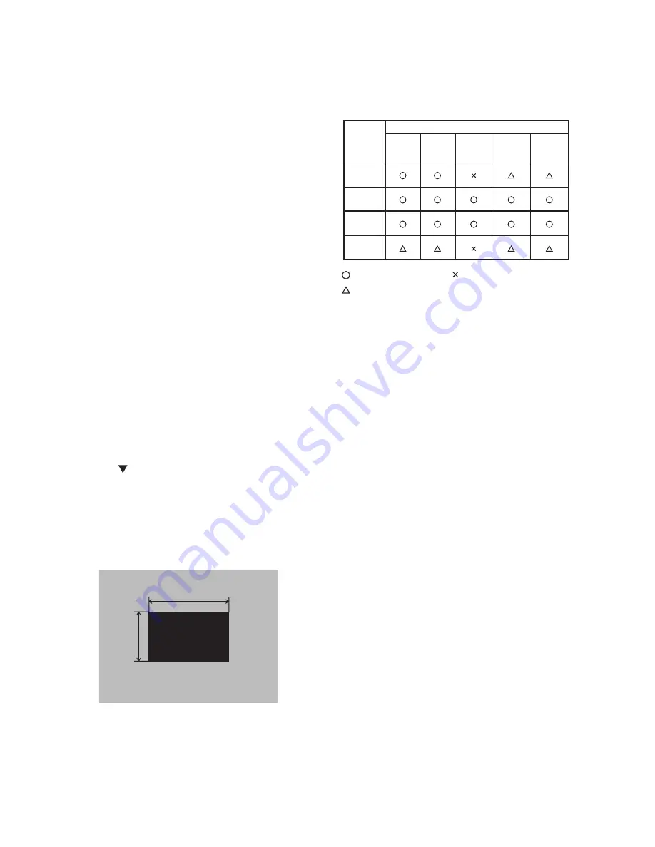
When any parts in the table 4-1 are changed,
choose the proper adjusting items with the chart.
Table 4-1: Relation between the replaced part and adjustment
���������
����
�����
����������
�������
����������
���������
����������
������
�������
����������
�����
����������
����������
��������
�����������
��������
������
��������
����
��������
�����
����
����
��������
����������
: means need for adjustment. : means not need for adjustment.
: means recommended.
4-1-2 Setting of condition before adjustment
1. Before starting adjustment, warm up the
projector for about 10 minutes.(Blank white)
2. Set Zoom Wide to Max. And project an image
with more than 1m (40 type) in diagonal size.
3. Normalizing the video adjustment.
(Press the [MENU] button of the Remote control
transmitter to display the MAIN menu, and then
press the [RESET] button. And select the
[DEFAULT]. Next, open MAIN menu and press
the [ ] key to display the PICTURE1 menu, then
press the [RESET] key to set to [DEFAULT].)
*note :The MAIN and PICTURE1 menu is not
reset with no signal.
4. Set the normal at OPT-WHISPER in the menu.
5. Reset KEYSTONE correction.
6. Perform all adjustments from the Adjustment
menu.
Perform the following operations to display the
Adjustment menu.
a. Press the [MENU] button of the Remote
control transmitter (the MAIN menu will
appear).
b. Next, press the [RESET] button one time.
And press the [RESET] button again for 5
seconds or more (the Adjustment menu will
appear).
ViewSonic Corporation
PJ650
Summary of Contents for PJ650
Page 12: ...11 PJ650 5 Troubleshooting Check points at trouble shooting ViewSonic Corporation PJ650 ...
Page 13: ...12 PJ650 ViewSonic Corporation PJ650 ...
Page 14: ...13 PJ650 ViewSonic Corporation PJ650 ...
Page 15: ...14 PJ650 ViewSonic Corporation PJ650 ...
Page 16: ...15 PJ650 ViewSonic Corporation PJ650 ...
Page 28: ...27 PJ650 7 Wiring diagram ViewSonic Corporation PJ650 ...
Page 29: ...28 PJ650 ViewSonic Corporation PJ650 ...
Page 30: ...29 PJ650 C3XM4 ViewSonic Corporation PJ650 ...
Page 31: ...30 PJ650 ViewSonic Corporation PJ650 ...
Page 32: ...31 PJ650 ViewSonic Corporation PJ650 ...
Page 33: ...32 PJ650 C3XM4 ViewSonic Corporation PJ650 ...
Page 34: ...33 PJ650 8 Disassembly diagram M Meter screw T Tapping screw ViewSonic Corporation PJ650 ...
Page 35: ...34 PJ650 M Meter screw T Tapping screw ViewSonic Corporation PJ650 ...
Page 37: ...36 PJ650 10 RS 232C communication ViewSonic Corporation PJ650 ...
Page 39: ...38 PJ650 Command data chart ViewSonic Corporation PJ650 ...
Page 40: ...39 PJ650 Command data chart ViewSonic Corporation PJ650 ...
Page 41: ...40 PJ650 Command data chart ViewSonic Corporation PJ650 ...
Page 42: ...41 PJ650 Command data chart ViewSonic Corporation PJ650 ...
Page 43: ...42 PJ650 11 Block diagram ViewSonic Corporation PJ650 ...
Page 44: ...43 PJ650 C3XM4 12 Connector connection diagram ViewSonic Corporation PJ650 ...
Page 49: ...A B C D E F G 5 4 3 2 1 6 6 5 4 3 2 1 PWB assembly DRIVE 1 ViewSonic Corporation PJ650 ...
Page 50: ...A B C D E F G 5 4 3 2 1 6 6 5 4 3 2 1 PWB assembly DRIVE 2 ViewSonic Corporation PJ650 ...
Page 51: ...A B C D E F G 5 4 3 2 1 6 6 5 4 3 2 1 PWB assembly DRIVE 3 ViewSonic Corporation PJ650 ...
Page 52: ...A B C D E F G 5 4 3 2 1 6 6 5 4 3 2 1 PWB assembly DRIVE 4 ViewSonic Corporation PJ650 ...
Page 53: ...A B C D E F G 5 4 3 2 1 6 6 5 4 3 2 1 PWB assembly DRIVE 5 ViewSonic Corporation PJ650 ...
Page 54: ...A B C D E F G 5 4 3 2 1 6 6 5 4 3 2 1 PWB assembly DRIVE 6 ViewSonic Corporation PJ650 ...
Page 55: ...A B C D E F G 5 4 3 2 1 6 6 5 4 3 2 1 PWB assembly DRIVE 7 ViewSonic Corporation PJ650 ...
Page 56: ...A B C D E F G 5 4 3 2 1 6 6 5 4 3 2 1 PWB assembly DRIVE 8 ViewSonic Corporation PJ650 ...
Page 57: ...A B C D E F G 5 4 3 2 1 6 6 5 4 3 2 1 PWB assembly DRIVE 9 ViewSonic Corporation PJ650 ...
Page 58: ...A B C D E F G 5 4 3 2 1 6 6 5 4 3 2 1 PWB assembly DRIVE 10 ViewSonic Corporation PJ650 ...
Page 59: ...A B C D E F G 5 4 3 2 1 6 6 5 4 3 2 1 PWB assembly SIGNAL 1 ViewSonic Corporation PJ650 ...
Page 60: ...A B C D E F G 5 4 3 2 1 6 6 5 4 3 2 1 PWB assembly SIGNAL 2 ViewSonic Corporation PJ650 ...
Page 61: ...A B C D E F G 5 4 3 2 1 6 6 5 4 3 2 1 PWB assembly SIGNAL 3 ViewSonic Corporation PJ650 ...


