background image

ViewSonic  PJ650

20

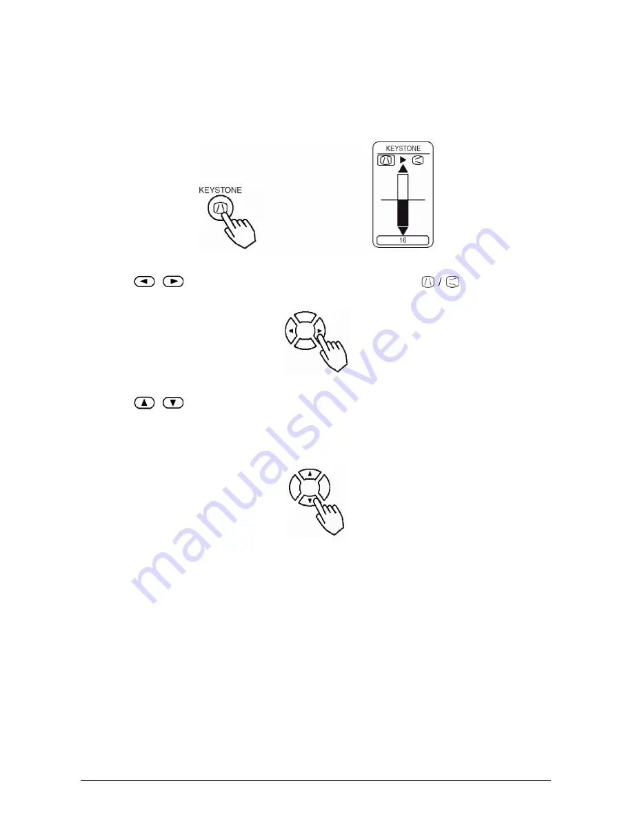
Correcting Keystrone Distortions

1

Press the KEYSTONE button

As illustrated on the right, a dialog box will appear on the screen to aid you in correcting the distortion.

2

Use the 

,  

buttons to select the direction of distortion to correct ( 

 )

3

Use the 

 buttons to correct the distortion

Press the KEYSTONE button again to close the dialog box and complete this operation. (Even if you don't 

do anything, the dialog box will automatically disappear after a few seconds.)

NOTE:

• This function may not be work well with some types of input signals.
• The adjustable range for correcting keystone distortions will vary with the type of input signal.

Summary of Contents for PJ650

Page 1: ...PJ650 User Guide Image Size 31 300 LCD Projector ...

Page 2: ...D Player or VCR 12 Connecting to a Display Monitor 13 Turning On The Power 14 Precautions 14 Turning Off The Power 15 Selecting an Input Signal 16 Adjusting the Volume 17 Temporarily Muting the Sound 17 Adjusting the Image Position 18 Using the Automatic Adjustment Feature 19 Correcting Keystrone Distortions 20 Using the Magnify Feature 21 Freezing the Screen 21 Signal Searching 22 Selecting the A...

Page 3: ...e Control Transmitter 34 Troubleshooting 35 On screen Messages 35 Panel Lamp Indicators 36 Problem Diagnostics 37 Specifications 38 Outline Dimension 38 Customer Support 39 Limited Warranty 40 VIEWSONIC Projector 40 Appendix 41 Power Cord Safety Guidelines 41 Compliance Information for U S A 42 Compliance Information for Canada 42 Compliance Information for European Countries 42 User Information f...

Page 4: ...s or omissions contained herein nor for incidental or consequential damages resulting from furnishing this material or the performance or use of this product In the interest of continuing product improvement ViewSonic Corporation reserves the right to change product specifications without notice Information in this document may change without notice No part of this document may be copied reproduce...

Page 5: ...ector to the point of destination To avoid penetration of foreign objects do not put the projector in a case or a bag together with any things except the accessories of the projector signal cables and connectors WARNING Before using this equipment read this manual thoroughly Always ensure that the equipment is used safely Projector Power Cord Video Audio Cable RGB Video Cable USB mouse cable Remot...

Page 6: ...DBY ON button Zoom knob Focus ring Air filter Elevator button Remote sensor Lens cap AUDIO IN R and L ports VIDEO IN port S VIDEO IN port RGB IN 1 and 2 ports AC power inlet Elevator button Power switch CONTROL port RGB OUT port USB port COMPONENT VIDEO port LAMP indicator TEMP indicator POWER indicator ...

Page 7: ...RCH button STANDBY ON button AUTO button BLANK button VOLUME button MUTE button KEYSTONE button MENU button RESET button ENTER button ESC button Cursor buttons POSITION button KEYBOARD buttons FREEZE button MAGNIFY buttons ASPECT button VIDEO button RGB button ...

Page 8: ...he remote control in an area free from obstacles that could block the remote control s output signal to the projector ATTENTION Precautions to observe when using the remote control Do not drop or otherwise expose the remote control to physical impact Do not get the remote control wet or place it on wet objects Doing so may result in malfunction Remove the batteries from the remote control and stor...

Page 9: ...ing the elevator buttons to adjust the elevator feet Adjusting the Projector s Elevator Feet You can use the elevator feet to make adjustments if the surface on which you need to set the projector is uneven or if you otherwise need to adjust the angle of projection The adjustment range of the elevator feet is 0 to 9 degrees 1 Press and hold in the elevator buttons 2 Raise or lower the projector to...

Page 10: ...80 2 0 95 2 4 114 2 9 2 6 46 116 90 2 3 107 2 7 129 3 3 3 7 51 131 100 2 5 119 3 0 143 3 6 3 7 57 145 120 3 0 143 3 6 172 4 4 3 9 69 174 150 3 8 180 4 6 216 5 5 4 11 86 218 200 5 0 240 6 1 288 7 3 6 15 114 290 250 6 3 300 7 6 361 9 2 7 18 143 363 300 7 5 360 9 2 433 11 0 9 22 171 435 Screen Size Inches m a Inches m Minimum Maximum b Inches cm c Inches cm 30 0 8 38 1 0 46 1 2 2 4 16 41 40 1 0 51 1 ...

Page 11: ... drivers as this projector is a Plug and Play monitor Plug and Play may not function properly with some type of computers Use the RGB IN 2 port if Plug and Play does not function correctly Function Projector Port Connection Cables RGB input RGB IN 1 Accessory RGB cable or optional RGB cable with D sub 15 pin shrink jack and inch thread screws RGB IN 2 RGB output RGB OUT USB mouse control USB Acces...

Page 12: ...r cord s specified voltage range Only use the power cord that came with the projector NEVER ATTEMPT TO DEFEAT THE GROUND CONNECTION OF THE THREEPRONGED PLUG Make sure that you firmly connect the power cord to the projector and wall outlet 1 Connect your devices to the projector Connect your computer VCR and or other devices you will be using to the projector 2 Insert the batteries into the remote ...

Page 13: ...and or damage to the device and or projector A component cable and some other cables have to be used with core set Use the accessory cable or a designated type cable for the connection For cables that have a core only at one end connect the core to the projector Secure the screws on the connectors and tighten NOTE When connecting the projector to a notebook computer set it so as to activate the RG...

Page 14: ...T display or to simultaneous LCD and CRT display For details on how this is done please refer to the laptop computer s instruction manual of the corresponding laptop computer NOTE Some computers may have multiple display screen modes The use of some of these modes may not be possible with this projector For some RGB input modes the optional Mac adapter is necessary Laptop computer Desktop computer...

Page 15: ...ViewSonic PJ650 12 Connecting to a DVD Player or VCR ...

Page 16: ...13 ViewSonic PJ650 Connecting to a Display Monitor RGB OUT RGB cable Display monitor RGB IN ...

Page 17: ...or will go to STANDBY mode and the POWER indicator will light to solid orange 3 Press the STANDBY ON button control panel or remote control The projector begins warming up and the POWER indicator blinks green The POWER indicator stops blinking and lights to solid green once the projector s power is completely on 4 Remove the lens cap The picture is projected NOTE Turn the power on off in right ord...

Page 18: ...p cools down Pressing the STANDBY ON button while the POWER indicator is blinking orange has no effect The system goes into STANDBY mode after cooling down the POWER indicator stops blinking orange and then lights to solid orange 3 Check that the POWER indicator stops blinking and lights to solid orange Switch the power switch to O OFF 4 Confirm that the POWER indicator has gone off and then attac...

Page 19: ...EO button Press this button to toggle between the devices connected to VIDEO IN SVIDEO IN and COMPONENT VIDEO As illustrated below each time you press the VIDEO button the projector switches between VIDEO IN S VIDEO IN and COMPONENT VIDEO Select the signal you wish to project Using the projector s control panel Press the INPUT button As illustrated below each time you press the INPUT button the pr...

Page 20: ...u don t do anything the dialog box will automatically disappear after a few seconds Temporarily Muting the Sound 1 Press the MUTE button As illustrated on the right a dialog box will appear on the screen indicating that you have muted the sound Press the VOLUME button to close the dialog box Even if you don t do anything the dialog box will automatically disappear after a few seconds Press the MUT...

Page 21: ... the position 2 Use the buttons to adjust the position When you want to initialize the position press the RESET button during adjustment Press the POSITION button again to close the dialog box and complete this operation Even if you don t do anything the dialog box will automatically disappear after a few seconds This function is only available for RGB IN 1 2 input ...

Page 22: ...t to its maximum size prior to attempting to use this feature Dark pictures may still be incorrectly adjusted Use a bright screen when adjusting 3 Automatic Adjustment for Video Input The signal type best suited for the respective input signal is selected automatically This feature is available only if VIDEO is set to AUTO in the INPUT menu NOTE The automatic adjustment operation requires approxim...

Page 23: ...ection of distortion to correct 3 Use the buttons to correct the distortion Press the KEYSTONE button again to close the dialog box and complete this operation Even if you don t do anything the dialog box will automatically disappear after a few seconds NOTE This function may not be work well with some types of input signals The adjustable range for correcting keystone distortions will vary with t...

Page 24: ...ically exit from MAGNIFY mode if either the INPUT SELECT AUTO ASPECT or VIDEO feature is used or if there is a change in the input signal s state Freezing the Screen 1 Press the FREEZE button The icon appears and the screen will freeze at the current image Press the FREEZE button again and the appears as the projector exits FREEZE MODE NOTE The projector will automatically exit FREEZE mode if eith...

Page 25: ...to the state it was in prior to the search Selecting the Aspect Ratio 1 Press the ASPECT button RGB IN 1 RGB IN 2 COMPONENT VIDEO HDTV signals 1125i 1035i 1080i 750p 4 3 16 9 VIDEO IN S VIDEO IN COMPONENT VIDEO Non HDTV signals 525i 525p 625i Temporarily Blanking the Screen 1 Press the BLANK button The input signal screen is shut off and a blank screen appears You can set the blank screen using th...

Page 26: ...ttons to select PICTURE 1 then press the or ENTER button 3 Select an item using the buttons then press the or the ENTER button The operation display of the selected item appears To adjust a numerical value press the or ENTER button again to switch to the single menu small display showing only the operation display area ex Adjusting SHARPNESS Use the buttons to select SHARPNESS then press the or th...

Page 27: ...onnecting go into BIOS system setup and select external mouse and disable the pointing devices In addition the mouse may not function if the computer does not have the needed utility program See your computer s hardware manual for details The USB control can be used with Windows 95 OSR 2 1 or higher It may not be possible to use the remote control depending on the computer s configurations and mou...

Page 28: ... separate menu Initialization of settings and or adjustments During operation press the RESET button Note that items whose functions are performed simultaneously with the operation of clock phase language selection automatic adjustment etc cannot be initialized End menu operations Press the MENU button or do not perform any operation for sev eral seconds Item Description BRIGHT Adjust Brightness L...

Page 29: ...VIDEO Clear Soft COLOR Adjust COLOR for VIDEO S VIDEO COMPONENT VIDEO Dark Light TINT Adjust Tint for VIDEO S VIDEO Green Red Item Description V POSITION Adjust Vertical Position for RGB Up Down H POSITION Adjust Horizontal Position for RGB Left Right H PHASE Adjust Horizontal Phase for RGB COMPONENT VIDEO Right Left Adjust to eliminate flicker H SIZE Adjust Horizontal Size for RGB Large Small If ...

Page 30: ...For a HDTV signal refer to the item HDTV below VIDEO Select Mode of Signal Type for VIDEO S VIDEO AUTO NTSC PAL SECAM NTSC4 43 M PAL N PAL Selecting AUTO mode activates and performs the AUTO function for VIDEO SVIDEO It automatically selects the proper mode from among those above Use this function if the image becomes unstable with VIDEO S VIDEO e g The image becomes irregular or lacks color AUTO ...

Page 31: ...ens Please make confirmation using the actual screen s Option screens Various colored non patterned plain screens displayed within the Menus The MyScreen and the ORIGINAL Screen will each change to a non patterned plain black color screen several minutes after being displayed START UP Selection of START UP Screen MyScreen ORIGINAL TURN OFF The START UP Screen may be voluntarily selected The START ...

Page 32: ...ayed 2 When the Move the capture area as you want message has been displayed pressing the ESC or RESET button will eliminate the static state of the picture and operations can be performed again from operation 1 The frame can be moved using the buttons After designating the screen you want to register pressing the ENTER button will initiate screen registration The registration process takes approx...

Page 33: ...ou have replaced the lamp And always reset the lamp time when replacing the lamp The message functions will not operate properly if the lamp time is not reset correctly After the lamp running reaches 2000 hours a warning message is displayed To maximize performance lamp replacement is recommended but won t shut the unit off The message display for 30 seconds when the PJ is turned on If we push any...

Page 34: ...he the gas that comes out of the projector vents or get it in your eyes or mouth Do not open the lamp cover while the projector is suspended from above This is dangerous since if the lamp s bulb has broken the shards will fall out when the cover is opened In addition working in high places is dangerous so ask your local dealer to have the lamp replaced even if the bulb is not broken If the indicat...

Page 35: ...o replace the lamp when you power up the projector the lamp needs to be replaced 1 Turn off the projector and unplug the power cord Allow the lamp bulb to cool for at least 45 minutes and prepare a new lamp 2 After making sure that the projector has cooled adequately slowly flip over the projector so that the bottom is facing up 3 Unscrew the 2 screws and remove the lamp cover 4 Unscrew the 1 scre...

Page 36: ...1 Turn off the projector then unplug the power cord 2 To clean a reusable filter carefully vacuum both sides of the filter area 3 If the filter is damaged and needs to be replaced contact your dealer or ViewSonic Corp Replace the old filter then put the grill back in place 4 To reset the Filter Timer turn on the projector power go to the Option menu then select filter timer Reset the filter timer ...

Page 37: ... soiling is severe dip a soft cloth in water or a neutral cleanser diluted in water and wipe lightly after wringing well Then wipe lightly with a soft dry cloth CAUTION Make sure to turn off the power and unplug the power cord before caring for the unit Please care fully read all the PJ650 Quick START GUIDE in this manual in order to care for your projector correctly Do not use cleaners or chemica...

Page 38: ... TIMER A note of precaution when cleaning the air filter After cleaning the filter operate FILTER TIME of the OPTION Menu then perform reset of the filter timer NO INPUT IS DETECTED ON There is no input signal Check the signal input connection and the status of the signal source SYNC IS OUT OF RANGE ON The horizontal or vertical frequencies of the inputted signal is out side of the operating range...

Page 39: ...hted or blinks Blinking of the red lamp Turned OFF Either there is no lamp and or lamp cover or either of these has not been properly fixed attached Turn the power OFF and wait approxi mately 45 minutes After the main unit has sufficiently cooled down please make confirmation of the attachment state of the lamp and lamp cover After performing any needed maintenance turn the power ON again if the s...

Page 40: ...ed Correctly connect the connection cord Pictures are dis played but no sounds are heard The electrical wiring to this unit is not correctly connected Correctly connect the connection cord The volume setting has been set at or adjusted to an extremely low level Adjust the VOLUME setting to a higher level MUTE is turned on Press the MUTE button to toggle the MUTE mode setting Sounds are heard but n...

Page 41: ...40V 1 3A Power consumption 240W typ Temperature range 0 35 C 32 95 F Operating Size 295 W x 87 5 H x 237 D mm 11 6 W x 3 4 H x 9 3 D inches Weight mass 2 7 kg 6 04 lbs Ports RGB Terminal RGB IN 1 2 2 VIDEO Terminal VIDEO IN 1 S VIDEO IN 1 COMPONENT VIDEO Y CB PB CR PR 1 AUDIO Terminal AUDIO IN R L 1 OUT Terminal RGB OUT 1 CONTROL Terminal CONTROL 1 USB 1 Optional Parts Lamp RLU 150 001 ViewSonic o...

Page 42: ...sonic com United Kingdom viewsoniceurope com T 0800 833 648 F 01293 643910 service eu viewsoniceurope com Europe Middle East Baltic countries and North Africa viewsoniceurope com Contact your reseller service eu viewsoniceurope com Australia and New Zealand viewsonic com au T 61 2 9929 3955 F 61 2 9929 8393 service au viewsonic com Singapore India and Southeast Asia viewsonic com sg T 65 6273 4018...

Page 43: ...wSonic Customer Support You will need to provide your product s serial number 2 To obtain warranted service you will be required to provide a the original dated sales slip b your name c your address d a description of the problem and e the serial number of the product 3 Take or ship the product freight prepaid in the original container to an authorized ViewSonic service center or ViewSonic 4 For a...

Page 44: ...rked with the letter L or coloured RED IMPORTANT NOTICE CONCERNING POWER CORD SELECTION The power cord set for this unit has been enclosed and has been selected according to the country of destination and must be used to prevent electric shock Use the following guidelines if it is necessary to replace the original cord set or if the cord set is not enclosed The female receptacle of the cord set mu...

Page 45: ... or an experienced radio TV technician for help FCC Warning To assure continued FCC compliance the user must use grounded power supply cord and the provided shielded video interface cable with bonded ferrite cores If a BNC cable is going to be used use only a shielded BNC 5 cable Also any unauthorized changes or modifications not expressly approved by the party responsible for compliance could voi...

Page 46: ...ViewSonic Corporation ...

Reviews: