background image

18

By pressing the [

PIP ON/OFF

] button on the remote control, you 

can change the mode in the order shown below: 

PIP

POP

SBS ASPECT

SBS FULL

OFF

The resolutions in the PIP and POP modes are configured as 

follows:
PIP SIZE  {

SMALL

}  : 320 x 240 pixels

 {

MIDDLE

}  : 480 x 320 pixels

 {

LARGE

}  : 640 x 480 pixels

POP SIZE : 474 x 355 pixels

NOTE:   The images displayed in the sub picture always fit the 

PIP sizes shown above irrespective of the aspect ratio 

of the input image.

4.2.5.  CONFIGURATION1 menu

PIP

1

2
3

SET

EXIT

MENU

1

:SEL

:NEXT

OFF TIMER

SCHEDULE

DATE AND TIME

CONFIGURATION1 RESET

CONFIGURATION1

:RETURN

:EXIT MENU

OFF

OFF TIMER

Set the display to turn itself off to standby mode within an 

amount of time specified.

The options are: {

OFF, 1HOUR ~ 24HOURS

} from currrent time.

SCHEDULE

This function allows you to program up to 7 (seven) different 

scheduled time intervals for the display to activate.
You can select: 
•  The time for the display to turn on and turn off.
•  The days in a week for the display to activate.
•  Which input source the display will use for each scheduled 

activation period.

NOTE:   You should set up current date and time in {

DATE AND 

TIME

} menu before using this function.
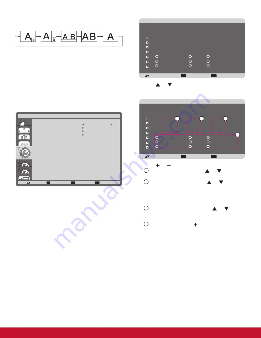
1.  Press [

SET

] button to enter the submenu.

EXIT

MENU

+-:SEL

:RETURN

:EXIT MENU

SCHEDULE

TODAY

1

2

3

4

5

7

6

2011 . 08 . 04

THU

20 : 19 : 55

ON


_

 : 

_


_

 : 

_


_

EVERY DAY

OFF

INPUT

WED

SAT

MON

THU

SUN

TUE

FRI

EVERY WEEK

2.  Press [ ] or [ ] button to select a schedule item (item 

number 1 ~ 7), and then press [

SET

] button to mark it the 

item number.

EXIT

MENU

+-:SEL

:RETURN

:EXIT MENU

SCHEDULE

TODAY

1

2

3

4

5

7

6

2011 . 08 . 04

THU

20 : 19 : 55

ON


_

 : 

_


_

 : 

_


_

EVERY DAY

OFF

INPUT

WED

SAT

MON

THU

SUN

TUE

FRI

EVERY WEEK

4

1

2

3

3.  Press [ ] or [ ] button to select the schedule: 

1


POWER-ON

 schedule: Press [ ] or [ ] button to set 

the hour and minute for the display to turn on.

2


  POWER-OFF

 schedule: Press [ ] or [ ] button to set 

the hour and minute for the display to turn off.

Select or leave an empty “

__

” for both the hour and minute 

slot if you do not want to use this power-on or power-off 

schedule.

3


 INPUT-SOURCE

 selection: Press [ ] or [ ] button to 

select an input source. If no input source is selected, 

the input source will remain the same as last selected.

4


 DATE

 schedule: Press [ ]  button to select which day 

in a week this schedule item will be take effect, and 

then press the [

SET

] button.

4.  For more schedule settings, press [

EXIT

] button and then 

repeat the steps above. A check mark in the box next to 

the number of the schedule item indicates that the selected 

schedule is in effect.

NOTES: 
•  The {

EVERY DAY

} selection in a schedule item takes priority 

over the other weekly schedules.

•  If the schedule overlap, the scheduled power-on time takes 

priority over scheduled power-off time.

•  If there are two schedule items programmed for the same 

time, the highest numbered schedule takes priority. For 

example, if schedule items #1 and #2 both set the display to 

power on at 7:00 AM and off at 5:00 PM, then only schedule 

item # 1 will take effect.

Summary of Contents for CDP3235

Page 1: ...a safe manner as well as registering your product for future service Warranty information contained in this User Guide will describe your limited coverage from ViewSonic Corporation which is also fou...

Page 2: ...off and on the user is encouraged to try to correct the interference by one or more of the following measures Reorient or relocate the receiving antenna Increase the separation between the equipment a...

Page 3: ...provided for your safety If the plug does not fit into your outlet consult an electrician for replacement of the outlet 9 Protect the power cord from being tread upon or pinched particularly at the pl...

Page 4: ...ed biphenyls PBB 0 1 0 1 Polybrominated diphenyl ethers PBDE 0 1 0 1 Certain components of products as stated above are exempted under the Annex of the RoHS Directives as noted below Examples of exemp...

Page 5: ...out prior written permission from ViewSonic Corporation Product Registration To meet your future needs and to receive any additional product information as it becomes available please register your pr...

Page 6: ...Equipment 9 3 1 Using the Switch Cover 9 3 2 Connecting External Equipment DVD VCR VCD 9 3 2 1 Using COMPONENT video input 10 3 2 2 Using HDMI video input 10 3 3 Connecting a PC 11 3 3 1 Using VGA inp...

Page 7: ...ONFIGURATION1 menu 18 4 2 6 CONFIGURATION2 menu 19 4 2 7 CONFIGURATION3 menu 20 4 2 8 ADVANCED OPTION menu 21 5 Input Mode 23 6 Cleaning and Troubleshooting 24 6 1 Cleaning 24 6 2 Troubleshooting 25 7...

Page 8: ...for Power switch cover M3 x 8 x 1 Exclusive of CDX5550 L BNC RCA adapter x 3 Video Signal Cable D SUB to D SUB Cable NOTES Please make sure that for all other regions apply a power cord that conforms...

Page 9: ...he display NOTE The long end side of the stand should face to the front while installing Thumbscrews Carrying handle Longer portions face the front Table stand CDP3235 STND 022 CDP4235 CDP4635 STND 02...

Page 10: ...odule 1 Power off the display 2 Remove the cover of OPS after take screw off 3 Insert OPS module and then fix by screw NOTE Keep the OPS cover for future use Screw Screw OPS To remove OPS Module 1 Pow...

Page 11: ...rocedures could result in damage to the equipment or injury to the user or installer Product warranty does not cover damage caused by improper installation 4 For the wall mounting kit use M6 mounting...

Page 12: ...o adjust the selected item while OSD menu is on 8 MENU button Return to previous menu while OSD menu is on or to activate the OSD menu when OSD menu is off NOTE Keyboard Control Lock Mode This functio...

Page 13: ...g a DVI HDMI cable 7 HDMI IN Connect the HDMI output of an AV device or the DVI D output of a PC by using a DVI HDMI cable 8 VGA IN D Sub Connect the computer VGA output 9 COMPONENT IN BNC Connect the...

Page 14: ...the OSD menu 8 AUTO ADJUST button Press to run the Auto Adjust function NOTE This button is functional for VGA input only 9 MUTE button Press to turn the mute function on off 10 VIDEO SOURCE button P...

Page 15: ...cause damage to your skin NOTE If you do not intend to use the remote control for a long period remove the batteries 2 3 3 Handling the remote control Do not subject to strong shock Do not allow water...

Page 16: ...d to prevent the display from being turned on or off accidentally To lock the cover into position 1 Align and insert the cover to the indentation located beside the main switch 2 Use the screw to lock...

Page 17: ...ting External Equipment DVD VCR VCD 3 2 1 Using COMPONENT video input Audio Output To AUDIO IN 2 3 DVD VCR VCD COMPONENT YPbPr COMPONENT YPbPr 3 2 2 Using HDMI video input DVD VCR VCD HDMI connector H...

Page 18: ...Using VGA input To VGA IN PC or IBM compatible From analog VGA output Mini D Sub 15 pin From audio output To AUDIO IN 1 2 3 3 3 2 Using DVI input From audio output To DVI IN PC or IBM compatible From...

Page 19: ...ct the USB cable on the display to a PC The touch module supports easy Plug and Play operations There is no need to install additional drivers on the PC 2 Install an OPS Open Pluggable Specification m...

Page 20: ...13 3 4 External Audio Connection 3 4 1 Connecting external speakers External speaker 3 4 2 Connecting an external audio device Stereo Amplifier RCA Audio In To AUDIO OUT...

Page 21: ...e VGA OUT connector of display 1 to the VGA IN connector of display 2 Connect the VIDEO OUT connector of display 1 to the VIDEO IN connector of display 2 To RS 232C IN RS 232C Cable PC To RS 232C OUT...

Page 22: ...T BRIGHTNESS CONTRAST SHARPNESS BLACK LEVEL TINT COLOR COLOR TEMPERATURE USER COLOR GAMMA SELECTION NATIVE NATIVE NOISE REDUCTION FILM MODE PICTURE RESET PICTURE RETURN EXIT MENU 50 50 70 50 BRIGHTNES...

Page 23: ...signal sources automatically ON Set the display to display the image automatically once a signal is connected OFF Once a signal is connected it can only be selected manually H POSITION Press the butto...

Page 24: ...IP 1 2 3 SET EXIT MENU PIP SEL NEXT PIP MODE PIP SIZE PIP AUDIO PIP H POSITION PIP V POSITION SUB INPUT PIP RESET PIP RETURN EXIT MENU SMALL MAIN AUDIO 100 0 VIDEO OFF PIP MODE Select the PIP Picture...

Page 25: ...EK 2 Press or button to select a schedule item item number 1 7 and then press SET button to mark it the item number EXIT MENU SEL RETURN EXIT MENU SCHEDULE TODAY 1 2 3 4 5 7 6 2011 08 04 THU 20 19 55...

Page 26: ...ION OSD Set the period of time the information OSD displayed on the upper right corner of the screen The information OSD will display when input signal is changed The information OSD will remain on th...

Page 27: ...dio CC2 Information related to the primary audio is displayed without sync CC3 Captions are displayed in sync with the secondary audio CC4 Information related to the secondary audio is displayed witho...

Page 28: ...put switching as NORMAL or QUICK NOTE The selection QUICK may cause a slight noise TERMINAL SETTING Select the mode to display the HDMI or DVI signal according to their signal format depending on thei...

Page 29: ...able and disable wake up from power saving mode by touch screen ADVANCED OPTION RESET Reset all settings in the ADVANCED OPTION menu to factory preset values 1 Press SET button to enter the submenu 2...

Page 30: ...ution Standard Resolution Active Resolution Refresh Rate Pixel Rate Aspect Ratio Stand for Mode H Pixels V Lines 720p 1280 720 50 Hz 74 25 MHz 16 9 Normally DVB Mode 60 Hz 1080i 1920 1080 25 Hz 74 25...

Page 31: ...ree cloth If the surface becomes dirty soak a soft lint free cloth in a mild detergent solution Wring the cloth to remove excess liquid Wipe the surface of the display to remove dirt Then use a dry cl...

Page 32: ...e is not correctly set Use the Zoom mode or Custom zoom function in the Screen menu to fine tune display geometry and time frequency parameter Can hear sound but no picture Improperly connected source...

Page 33: ...MAX Video 720p 1080p 1920 x 1080 60 Hz WUXGA Audio 48 KHz 2 Channel L R Supports LPCM only DVI D Input DVI D jack Digital RGB TMDS Video VGA Input D Sub Jack x 1 15 pin Analog RGB 0 7V p p 75 H CS V T...

Page 34: ...ature Operational 0 40 C Storage 20 60 C Humidity Operational 20 80 RH No condensation Storage 5 95 RH No condensation Altitude Operational 0 3 000 m Storage Shipment 0 9 000 m Internal Speaker Item S...

Page 35: ...only DVI D Input DVI D jack Digital RGB TMDS Video VGA Input D Sub Jack x 1 15 pin Analog RGB 0 7V p p 75 H CS V TTL 2 2k SOG 1V p p 75 MAX 720p 1080p 1920 x 1080 60 Hz WUXGA VGA Output D Sub Jack x...

Page 36: ...RH No condensation Altitude Operational 0 3 000 m Internal Speaker Item Specifications Output 10W 10W RMS Impedance 8 Output Sound Pressure 82 dB W M Frequency Response 160 Hz 13 KHz CDP4235 T Touch...

Page 37: ...D Input DVI D jack Digital RGB TMDS Video VGA Input D Sub Jack x 1 15 pin Analog RGB 0 7V p p 75 H CS V TTL 2 2k SOG 1V p p 75 MAX 720p 1080p 1920 x 1080 60 Hz WUXGA VGA Output D Sub Jack x 1 15 pin...

Page 38: ...No condensation Altitude Operational 0 3 000 m Internal Speaker Item Specifications Output 10W 10W RMS Impedance 8 Output Sound Pressure 82 dB W M Frequency Response 160 Hz 13 KHz CDP4635 T touch spec...

Page 39: ...Supports LPCM only DVI D Input DVI D jack Digital RGB TMDS Video VGA Input D Sub Jack x 1 15 pin Analog RGB 0 7V p p 75 H CS V TTL 2 2k SOG 1V p p 75 MAX 720p 1080p 1920 x 1080 60 Hz WUXGA VGA Output...

Page 40: ...al 0 40 C Storage 20 60 C Humidity Operational 20 80 RH No condensation Storage 5 95 RH No condensation Altitude Operational 0 3 000 m Internal Speaker Item Specifications Output 10W 10W RMS Impedance...

Page 41: ...a Columbia www viewsonic com la T 01800 9 157235 soporte viewsonic com Latin America Mexico www viewsonic com la T 001 8882328722 soporte viewsonic com Renta y Datos 29 SUR 721 COL LA PAZ 72160 PUEBLA...

Page 42: ...failure to follow instructions supplied with the product b Any damage of the product due to shipment c Removal or installation of the product d Causes external to the product such as electrical power...

Page 43: ...customer by any other party 4 Repair or attempted repair by anyone not authorized by ViewSonic Effect of state law This warranty gives you specific legal rights and you may also have other rights whic...

Page 44: ...iving service under warranty contact ViewSonic Customer Support Please refer to the attached Customer Support page You will need to provide your product s serial number so please record the product in...

Page 45: ...obales com Cuernavaca Compusupport de Cuernavaca SA de CV Francisco Leyva 178 Col Miguel Hidalgo C P 62040 Cuernavaca Morelos Tel 01 777 3180579 01 777 3124014 E Mail aquevedo compusupportcva com Dist...

Page 46: ...39...

Reviews: