background image

7

D

13c

9

145

3 2 1

7 6 5 4

X3

X4

A

B

C

4

3

2

1

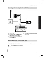
A

Vitotrol 300A

B

2 or 3-pole plug 

aVG

 (to the control

unit or the KM BUS distributor)

C

Weather-compensated control unit
with terminals X3

D

Separate room temperature sensor
(accessory)

Connecting several remote control units

Up to 2 remote control units can be connected to a boiler control unit, incl. a
Vitotrol 200A 

and

 a Vitotrol 300A. 

Vitotrol 200A installation instructions

Installation sequence

Installing and connecting the Vitotrol 300A

 (cont.)

5458 093 GB

Installation


Summary of Contents for VITOTROL 300A

Page 1: ...Installation and service instructions for contractors VIESMANN Vitotrol 300A Remote control part no 7438 364 VITOTROL 300A 5458 093 GB 3 2010 Please keep safe ...

Page 2: ...f accidents all legal instructions regarding envi ronmental protection the Code of Practice of relevant trade associations all current safety regulations as defined by DIN EN DVGW TRGI TRF VDE and all locally applicable standards Gas Safety Installation Use Regu lations the appropriate Building Regulation either the Building regulations the Building Regulation Scotland Building Regulations Norther...

Page 3: ...static dis charges Touch earthed objects such as heating or water pipes to dis charge static loads Repair work Please note Repairing components which ful fil a safety function can compro mise the safe operation of your heating system Replace faulty components only with original Viessmann spare parts Ancillary components spare and wearing parts Please note Spare and wearing parts which have not bee...

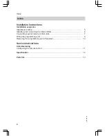
Page 4: ...ling and connecting the Vitotrol 300A 6 Connecting several remote control units 7 Fitting the programming unit 9 Removing the programming unit if required 10 Service instructions Commissioning Configuring the remote control 11 Specification 12 Parts list 13 Index Index 5458 093 GB ...

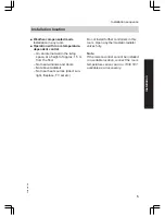
Page 5: ...s and doors Not above radiators Not near heat sources direct sun light fireplace TV set etc Do not install further controllers in this room Open any thermostatic radiator valves fully Note If the remote control cannot be installed in a suitable location connect the room temperature sensor part no 7438 537 available as an accessory Installation sequence Installation location 5458 093 GB Installatio...

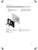
Page 6: ...heating or water pipes to discharge static loads Connection Two core cable with a cross section of at least 0 75 mm cores may be inter changed Cable length up to 50 m Note Never route the cable to the remote con trol immediately next to 230 400 V cables Installation sequence Installing and connecting the Vitotrol 300A 5458 093 GB ...

Page 7: ...trol unit with terminals X3 D Separate room temperature sensor accessory Connecting several remote control units Up to 2 remote control units can be connected to a boiler control unit incl a Vitotrol 200A and a Vitotrol 300A Vitotrol 200A installation instructions Installation sequence Installing and connecting the Vitotrol 300A cont 5458 093 GB Installation ...

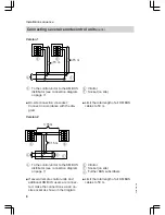
Page 8: ...bles to 50 m Version 2 A B D C B 15 m 15 m 4 3 2 1 4 3 2 1 A To the control unit or to the KM BUS distributor see connection diagram on page 7 B Vitotrol C Socket on site D Further BUS subscribers If several remote control units and additional KM BUS users are connec ted make the connections via an on site socket as shown in the diagram Limit the total length of all KM BUS cables to 50 m Installat...

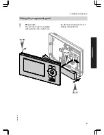
Page 9: ...ease note The remote control is supplied with power by the control unit Do not insert batteries into the battery compartment 1 3 2 Installation sequence Fitting the programming unit 5458 093 GB Installation ...

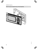
Page 10: ...10 2 1 Installation sequence Removing the programming unit if required 5458 093 GB ...

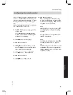
Page 11: ...lled the room tempera ture sensor to be controlled 5 With select Save with OK 6 OK as confirmation 7 With select Save Yes 8 OK as confirmation The operating state of the heating system is transferred A running bar appears in the display This process may take several minutes Note Whilst the bar is shown pressing can display the configured heating circuits Configuration has completed when the bar di...

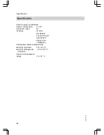
Page 12: ...class III IP rating IP 30 to EN 60529 ensure through appropriate design and installation Permissible ambient temperature during operation 0 to 40 C during storage and transport 20 to 65 C Set room temperature range 3 to 37 C Specification Specification 5458 093 GB ...

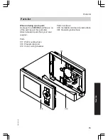
Page 13: ...s per this parts list Obtain standard parts from your local supplier Parts 017 Wall mounting base 018 Programming unit 019 Cover wiring chamber Parts not shown 080 Installation and service instructions 081 Operating instructions 017 018 019 Parts list Parts list 5458 093 GB Service ...

Page 14: ...14 5458 093 GB ...

Page 15: ...15 5458 093 GB ...

Page 16: ... 1952 675000 Fax 44 1952 675040 E mail info uk viessmann com Viessmann Werke GmbH Co KG D 35107 Allendorf Telephone 49 6452 70 0 Fax 49 6452 70 2780 www viessmann com 5458 093 GB Subject to technical modifications Printed on environmentally friendly chlorine free bleached paper ...

Reviews: