background image

8

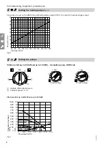
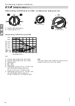
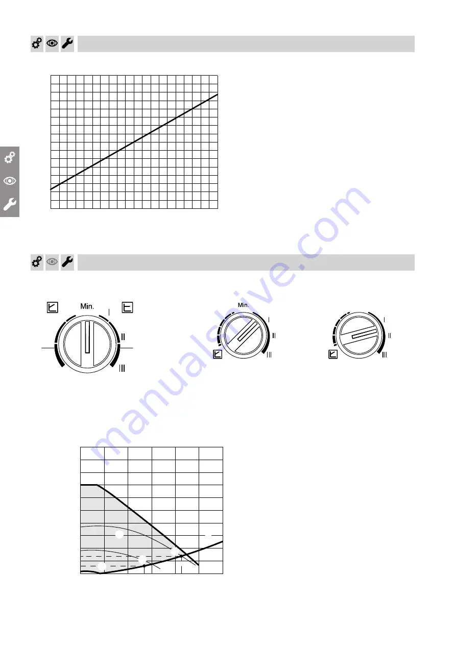
Flow rate to be set on the DHW side (with temperature spread 10/60 °C) subject to heat exchanger output

40 60

80 100 120 140

0

10

20

30

40

50

60

70

80

Flow rate in l/min

HE output in kW

160 180 200 220 240

Fig.2

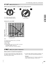
Setting the pumps

Vitotrans 222 (up to 80 kW and up to 120 kW) - circulation pump, DHW side

A

B

A

Variable differential pressure

B

Constant speed I, II, III


1

4

7

80 kW setting

1

4

7

Min.

120 kW setting

Vitotrans 222 up to 80 kW and up to 120 kW

0.5

1.0

1.5

2.0

2.5

3.0

10

20

30

40

50

60

70

80

90

100

100

200

300

400

500

600

700

800

900

1000

0

mbar

kPa 0

0

Flow rate in m³/h

Pressure drop/head

D

F

A

E

B

C

Fig.3

Commissioning, inspection, maintenance

Setting the heating output

 (cont.)

5549 892 GB

Summary of Contents for VITOTRANS 222

Page 1: ...Service instructions for contractors VIESMANN Vitotrans 222 Heat exchanger set for cylinder loading system For applicability see the last page VITOTRANS 222 5549 892 GB 4 2014 Please keep safe ...

Page 2: ...l locally applicable standards a ÖNORM EN and ÖVE c SEV SUVA SVTI and SWKI Working on the system Isolate the system from the power supply e g by removing the separate fuse or by means of a mains isolator and check that it is no longer live Safeguard the system against reconnection Please note Electronic assemblies can be damaged by elec trostatic discharge Prior to commencing any work touch earthe...

Page 3: ...ntenance Steps commissioning inspection and maintenance 5 3 Display and troubleshoot ing LED at the HE circulation pump 14 4 Parts lists Parts list 15 5 Commissioning service reports 17 6 Specification 18 7 Certificates Declaration of conformity 19 Index Index 5549 892 GB ...

Page 4: ...se presupposes that a fixed installation in conjunction with permissible system specific compo nents has been carried out Commercial or industrial usage for a purpose other than heating the building or DHW shall be deemed inappropriate Any usage beyond this must be approved by the man ufacturer for the individual case Incorrect usage or operation of the appliance e g the appliance being opened by ...

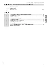
Page 5: ...art up 6 4 Setting the heating output 6 5 Setting the pumps 8 6 Setting the cylinder temperature 11 7 Shutting down the system 12 8 Checking the function of the safety valve 9 Inspection and maintenance of the cylinder loading system 12 10 Restarting the system Commissioning inspection maintenance Steps commissioning inspection and maintenance 5549 892 GB ...

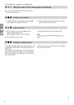
Page 6: ...er supply 3 Monitor initial heat up of the Vitotrans 222 Note For the adjustment of the DHW temperature see page 11 Setting the heating output The required heating output see diagram below is set by adjusting the flow rates on the heating water and DHW side The flow rate can be influenced via the speed of the integral pumps see from page 8 and on the DHW side via the integral line regulating valve...

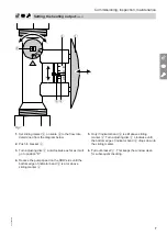
Page 7: ...duce the pump speed on the DHW side until the bottom edge of indicator band E is at or above sliding marker A 5 Only if indicator band E is still above sliding marker A Turn adjusting disc D clockwise until the bottom edge of indicator band E drops down to the sliding marker 6 Pull out bracket C This keeps the window clean for subsequent checking Commissioning inspection maintenance Setting the he...

Page 8: ...to 80 kW and up to 120 kW circulation pump DHW side A B A Variable differential pressure B Constant speed I II III 1 4 7 80 kW setting 1 4 7 Min 120 kW setting Vitotrans 222 up to 80 kW and up to 120 kW 0 5 1 0 1 5 2 0 2 5 3 0 10 20 30 40 50 60 70 80 90 100 100 200 300 400 500 600 700 800 900 1000 0 mbar kPa 0 0 Flow rate in m h Pressure drop head D F A E B C Fig 3 Commissioning inspection mainten...

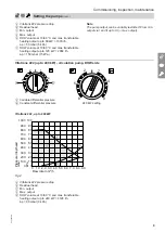
Page 9: ...p to 240 kW circulation pump DHW side 2 5 8 1 4 8 A Variable differential pressure B Constant differential pressure 2 5 8 1 4 8 240 kW setting Vitotrans 222 up to 240 kW E A D 3 0 6 0 9 0 10 20 30 40 50 60 70 80 90 100 100 200 300 400 500 600 700 800 900 1000 0 mbar kPa 0 0 Flow rate in m h Pressure drop head 1 0 2 0 4 0 5 0 7 0 8 0 B C Fig 4 A Vitotrans 222 pressure drop B Residual head C Min out...

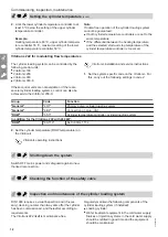
Page 10: ...0 0 5 E C D F G B A Fig 5 A Pressure drop Vitotrans 222 up to 80 kW B Pressure drop Vitotrans 222 up to 120 kW C Residual head D Min output E Max output F Heating water volume at TF TR 75 35 C and max transferable heating output up to 80 kW 1720 l h Δp 70 mbar 7 kPa G Heating water volume at TF TR 75 35 C and max transferable heating output up to 120 kW 2580 l h Δp 130 mbar 13 kPa Note The pump ou...

Page 11: ... Min output D Max output E Heating water volume at TF TR 75 35 C and max transferable heating output up to 240 kW 5160 l h Δp 250 mbar 25 kPa Setting the cylinder temperature Vitotrans 222 for constant flow temperatures The upper cylinder temperature controller starts cylin der heating while the lower cylinder temperature con troller stops cylinder heating 1 Limit the upper cylinder temperature co...

Page 12: ... the Vitotronic For this carry out the following settings in code 2 Group Code Function General 4C 1 Primary pump cylinder loading system General 4E 2 Connection on plug gSA1 DHW 55 3 Cylinder temperature controller cylinder loading system In addition for the Vitotrans 222 with 240 kW DHW 6A 113 Set runtime 113 s 2 Set the cylinder temperature DHW temperature on the Vitotronic Vitotronic operating...

Page 13: ...lter Replace filter element on non backwashing filters every 6 months visual inspection every 2 months On backwashing filters backwash every 2 months Service documents from the manufacturers Restarting the system Commissioning inspection maintenance Inspection and maintenance of the cylinder cont 5549 892 GB ...

Page 14: ...en removed Undervoltage 160 V Overvoltage 253 V Check power supply 195 V U 253 V Motor temperature too high Check ambient and heat transfer medium tempera tures Flashes red Circulation pump switched off blocked Circulation pump does not start automatically Replace the circulation pump Is OFF No power Check connecting cable LED faulty Check whether the circula tion pump is running PCB faulty Replac...

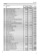
Page 15: ...7836448 7836448 7836448 0010 Control valve DN 25 PN 16 VRG3 7835293 7835293 0010 Control valve DN 32 PN 16 VRG3 7835292 0011 Pump ball valve DN 25 7820399 7820399 0011 Pump ball valve DN 32 7820400 0012 Pump ball valve DHW DN 25 7840889 7840889 0012 Pump ball valve DHW DN 32 7840890 0013 Tee sizes 1 2 7835283 7835283 0013 Tee size 3 7835278 0014 Pipe section sizes 1 2 7835284 7835284 0014 Pipe sec...

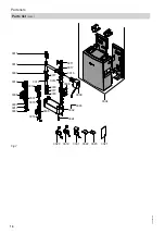
Page 16: ...0013 0009 0011 0017 0010 0003 0018 0006 0003 0016 0005 0002 0024 0017 0017 0003 0003 0020 0019 0001 0022 0023 0021 0003 0008 0012 0012 0003 0017 0014 0004 0015 0007 Fig 7 Parts lists Parts list cont 5549 892 GB ...

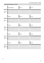
Page 17: ...rvice Service date by Service Service Service date by Service Service Service date by Service Service Service date by Service Service Service date by Commissioning service reports Commissioning service reports 5549 892 GB ...

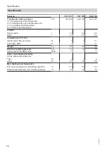
Page 18: ... 3 4 0 DHW l 1 7 2 3 4 0 Connections DIN 2999 Heating water flow and return R 1 1 1 Cold water DHW R 1 1 1 Weight kg 25 27 60 Permiss operating pressure Heating water and DHW sides bar MPa 10 1 10 1 10 1 Power consumption per pump On the primary secondary side Min W 3 3 8 Max W 45 45 130 Max heating water temperature With mixer assembly for modulating operation C 110 110 110 Without mixer assembly...

Page 19: ...h the following standards EN 60 335 1 EN 60 335 2 51 EN 61 000 6 3 EN 61 000 6 1 In accordance with the following Directives this product is designated _ 2004 108 EC 2006 42 EC 2006 95 EC Allendorf 10 February 2014 Viessmann Werke GmbH Co KG Authorised signatory Manfred Sommer Certificates Declaration of conformity 5549 892 GB ...

Page 20: ...Limited Hortonwood 30 Telford Shropshire TF1 7YP GB Telephone 44 1952 675000 Fax 44 1952 675040 E mail info uk viessmann com Viessmann Werke GmbH Co KG D 35107 Allendorf Telephone 49 6452 70 0 Fax 49 6452 70 2780 www viessmann com 5549 892 GB Subject to technical modifications ...

Reviews: