36
0
8.
Record the actual value in the report.
Implement measures as indicated in the table
below.
0
9.
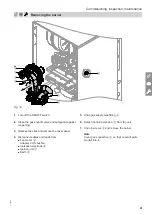
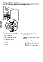
Shut down the boiler. Close the gas shut-off valve.
10.
Remove the pressure gauge. Tighten the screw in
test connector
B
.
11.
Open the gas shut-off valve and start the appli-
ance.
Danger
Gas escaping from the test connector leads
to a risk of explosion.
Check gas tightness at test connector
B
.
12.
Fit cover panel
A
.
Supply pressure (flow pressure)
Measures
For natural gas
For LPG
H
E, E+, M
L, LL, S, K
Lw
Below 13 mbar
(1.3 kPa)
Below
17 mbar
(1.7 kPa)
Below
18 mbar
(1.8 kPa)
Below
16 mbar
(1.6 kPa)
Below
25 mbar
(2.5 kPa)
Do not start the boiler. Notify
your gas supply utility or LPG
supplier.
13 to 33 mbar
(1.3 to
3.3 kPa)
17 to 33 mbar
(1.7 to
3.3 kPa)
18 to 33 mbar
(1.8 to
3.3 kPa)
16 to 33 mbar
(1.6 to
3.3 kPa)
25 to
57.5 mbar
(2.5 to
5.75 kPa)
Start the boiler.
Above 33 mbar
(3.3 kPa)
Above
33 mbar
(3.3 kPa)
Above
33 mbar
(3.3 kPa)
Above
33 mbar
(3.3 kPa)
Above
57.5 mbar
(5.75 kPa)
Install a separate gas pressure
governor upstream of the sys-
tem. Set the pre-charge pres-
sure to 20 mbar (2.0 kPa) for
natural gas and 50 mbar
(5.0 kPa) for LPG. Notify your
gas supply utility or LPG suppli-
er.
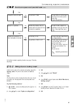
Function sequence and possible faults
Display
Measure
Control unit issues a heat
demand
No
Increase set value. Ensure
heat transfer.
Yes
Fan starts
No
Fault F.59, F.457
Check connection cables on
fan. Check power supply on
fan.
Yes
Ignition
No
Fault F.359
Check ignition module (con-
trol voltage 230 V across
plugs "X18.1" and "X18.3" on
the burner control units).
Check the gas supply.
Yes
Gas train opens
No
Fault F.357, F.368
Check the gas supply pres-
sure.
Commissioning, inspection, maintenance
Checking the static pressure and supply pressure
(cont.)
6130884


