


Connections
Connections
8
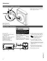
Verification of Anode Connection
Check proper connection of grounding
cable at magnesium anode.
Grounding cable
Magnesium anode
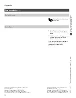
Boiler Water Connections
Vitocell 100
DHW tank temperature sensor
and/or aquastat
Air vent
Flow check valve, spring-loaded
DHW recirculation pump
Boiler water supply
Boiler water return
Hot water heating boiler
Max. supply temp.
230
º
F / 110
º
C
. . . .
Max. DHW temp.
150
º
F / 65.6
º
C
. . . . . .
Max. tank operating pressure
H
heating water side
150 psig
. . . . . . . . . . . . . .
H
DHW side
150 psig
. . . . . . . . . . . . . . . . . . . . . . . . . . . . . . .
Max. tank testing pressure
H
heating water side (primary)480 psig
H
DHW side (secondary)
300 psig
. . . . . . .
1.
Connect heating water side (primary)
connections using supplied adaptors.
See Installation Instruction
Supplement for fittings
supplied with tank.
2.
Control heat supply to the tank
according to illustration on the left.
3.
Pipe supply connections with upward
slopes and install an air vent valve at
highest point.
4.
Install supplied tank temperature
sensor into sensor well (see page 7).
5.
Insulate pipe connections.
5167
514
v1.1
5167
514
v1.1
The operating aquastat and any
secondary high limit aquastat of the
tank must be set such that the DHW
temperature inside the tank never
exceeds 203 °F / 95 °C.
WARNING


