background image

7

Checking the gas type

1. 

Determine the gas type and Wobbe
index (Wo) from your gas supply util-
ity.
■ With the 

natural gas E setting

, the

boilers can be operated in the
Wobbe index range 12.0 to
16.1 kWh/m

3

 (43.2 to 58.0 MJ/m

3

).

■ With the 

natural gas LL setting

,

the boilers can be operated in the
Wobbe index range 10.0 to
13.1 kWh/m

3

 (36.0 to 47.2 MJ/m

3

)

(not in 

a

 and 

c

).

2. 

In the delivered condition, the burner
is set up for natural gas E. If required,
convert the burner to the other gas
type in accordance with details provi-
ded by your gas supply utility (see
page 7).

3. 

Record the gas type in the report (on
page 45).

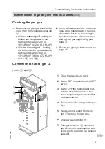
Conversion to natural gas LL

(not in 

a

 and 

c

)

C

B

A

0

1. 

Close the gas shut-off valve.

0

2. 

Switch OFF the control unit ON/OFF
switch.

0

3. 

Switch OFF the main isolator (out-
side the installation room) or the
power supply and prevent unauthor-
ised reconnection.

0

4. 

Release the cable fixings on the gas
pipe.

0

5. 

Release compression fittings 

A

and 

C

 remove the gas pipe.

0

6. 

Unscrew gas restrictor 

B

.

0

7. 

Take gas restrictor 

B

 for natural

gas LL from the pack supplied and
screw on (for diameter see table on
page 46).

Commissioning, inspection, maintenance

Further details regarding the individual steps

 (cont.)

5692 488 GB

Summary of Contents for MatriX

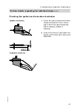
Page 1: ...ors VIESMANN MatriX radiant burner Type VMIII Pressure jet gas burner for the Vitocrossal 300 type CM3 Rated output 80 to 130 87 to 142 kW For applicability see the last page MatriX radiant burner 569...

Page 2: ...accidents all legal instructions regarding envi ronmental protection the Code of Practice of relevant trade associations all current safety regulations as defined by DIN EN DVGW TRGI TRF VDE and all...

Page 3: ...tatic dis charges Touch earthed objects such as heating or water pipes to dis charge static loads Repair work Please note Repairing components which ful fil a safety function can compro mise the safe...

Page 4: ...6 Air pressure switch 21 Burner control unit Burner control unit MPA 51 22 Troubleshooting Diagnosis 29 Burner control unit flow chart 35 Burner control unit connection diagram 37 Component overview 3...

Page 5: ...flue gas temperature 9 Checking the ionisation current 14 10 Shutting down the system 15 11 Checking the burner gauze assembly 16 12 Checking the ignition and ionisation electrodes 17 13 Cleaning the...

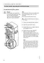
Page 6: ...shut off valve 3 Switch ON the main isolator outside the installation room 4 Switch ON the system ON OFF switch B at the control unit If fault indicator lamp A on the con trol unit illuminates and dis...

Page 7: ...details provi ded by your gas supply utility see page 7 3 Record the gas type in the report on page 45 Conversion to natural gas LL not in a and c C B A 01 Close the gas shut off valve 02 Switch OFF t...

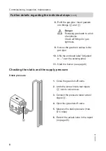
Page 8: ...el 11 Start the burner see page 6 Checking the static and the supply pressure Static pressure A 1 Close the gas shut off valve 2 Undo the screw inside test nipple A but do not remove 3 Connect the pre...

Page 9: ...age 45 4 Close the gas shut off valve 5 Remove the pressure tester and close test nipple A Supply pressure flow pressure Measures below 15 mbar Make no adjustments and contact the gas supply utility 1...

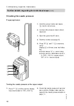
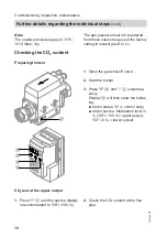
Page 10: ...y C will then show the follow ing Under status d control stop Under service Modulation level in 00 100 upper output 00 0 lower output Testing the nozzle pressure at the upper output 1 Press E until th...

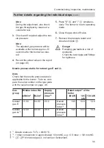
Page 11: ...ittings for tightness Nozzle pressure table for natural gas E and LL Note Check that the nozzle pressure table is applicable for the burner To do so com pare the serial number on the type plate with t...

Page 12: ...t off valve 2 Start the burner 3 Press S D and C simultane ously Display B will then show the follow ing Under status d control stop Under service Modulation level in 00 100 upper output 00 0 lower ou...

Page 13: ...t the lower output A B C D E 1 Press C until the service display has decremented to 00 lower out put 2 Check the CO2 content at the flue pipe Burner output in kW Permissible CO2 content in 80 8 5 to 9...

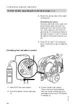
Page 14: ...3 repeat the steps for the upper and lower out put 5 Press S D and C simultane ously The burner is now in operating mode Checking the ionisation current A C D B 01 Switch OFF the main isolator 02 Pull...

Page 15: ...ve has been opened and during oper ation the ionisation current should be at least 3 A 09 Record the actual value in the report on page 45 10 Switch the main isolator OFF remove the test equipment and...

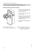
Page 16: ...he wire mesh of burner gauze assembly A for damage Slight wavy deformations of burner gauze assembly A are OK 4 Replace burner gauze assembly A if required Installation instructions Burner component r...

Page 17: ...he ignition electrodes and the ionisation electrode for the correct gap to the burner gauze assembly and for damage replace if required 2 Close the boiler door and tighten the screws on the boiler doo...

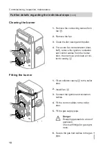
Page 18: ...ir col lector casing A Fitting the burner B A 1 Fit air collector casing A to the boiler door 2 Install fan B 3 Connect the ignition and ionisation cables 4 Fit the control cables to the boiler door 5...

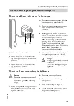
Page 19: ...Otherwise there is a leak If this is the case return the gas train to Viessmann Werke for testing 7 After the test close both test nipples by tightening the relevant screws Danger Escaping gas leads...

Page 20: ...tion card Hand the system user their part for safekeeping Retain the heating contractor s part 2 File all parts lists operating and serv ice instructions in the folder and hand this over to the system...

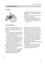
Page 21: ...e range The fault shutdown is shown with fault display L on the burner control unit see page 22 and 29 and cannot be rectified by pressing reset The fault shutdown can only be rectified by shutting do...

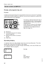
Page 22: ...seven segments each Four keys enable adjustments to be made at the different operating levels A DIP switch on the back of the display and programming unit enables burner parameters to be configured f...

Page 23: ...Service Pre purge Status Service Pre ignition Status Service Safety time Status Service Flame established Status Service Operation with flame Status Service Post purge Status Service Standby Burner co...

Page 24: ...heat demand must be issued by the control unit The service display shows the current modulation level in Display d 00 Lower output d 00 Upper output with full stop behind last digit Status Service 1 P...

Page 25: ...1 2 3 4 5 6 7 8 ON Parameter set 2 130 142 kW 1 2 3 4 5 6 7 8 ON ON Parameter set 7 91 100 kW 1 2 3 4 5 6 7 8 ON Acknowledging a parameter set A flashing P is shown under Status if a parameter set is...

Page 26: ...This display will be terminated if no key is pressed within 20 s Status Service 1 Press S and a simultaneously Status Service 2 Press S The selected parameter set is dis played under Service 3 Press S...

Page 27: ...ice 3 Press the reset button The operating display will be shown again Fault memory The six most recent faults are saved and can be called up The order of scans ranges from the most recent to the earl...

Page 28: ...most recent fault Display under Status Fault 1 6 Most recent fault Sixth most recent fault The relevant fault code is displayed under Service 3 Press S Then the operating display will be shown again...

Page 29: ...nowledging a parameter set page 25 General process errors Fault code System characteris tics Cause Measures 20 Fan pressure is pro duced during the air pressure switch idle state check Wind influence...

Page 30: ...e selected Adjust the gas type see page 7 25 No flame signal after safety time ionisation flame monitor reports no flame signal Gas train does not open Check gas train and replace if required 25 No fl...

Page 31: ...es during operation Combustion char acteristics not ideal Adjust burner see from page 12 29 Burner control unit fault Internal fault of gas pressure switch input Replace burner control unit 2A Burner...

Page 32: ...t in operation is not reached Fan faulty cable 100a faulty or broken Check cable and replace cable 100a or fan if required 37 Fan does not reach its set speed Fan faulty cable 100 or 100a faulty or br...

Page 33: ...r excess Adjust gas throughput in accord ance with rated boiler output Condensate banked up in flue gas system Check condensate drain Incorrect flue gas draught Check flue gas draught Burner restarts...

Page 34: ...hput Adjust gas throughput in accord ance with rated boiler output Check condition of boiler secondary heating surfaces clean if required Whining noises Incorrect CO2 set tings Adjust burner in accord...

Page 35: ...Ignition solenoid valve servomotor Flame signal Gas pressure limiter Choke valve option Y2 Safety temperature limiter Input Output Output Input Output Output Output Input Input 01 Fault ON OFF ON or O...

Page 36: ...s 08 Pre ignition 2 s 09 Safety time start safety time A enabling the safety valves at the start of safety time A safety time operation 1 s no gas pressure switch monitoring 2 to 10 s 10 Stabilising...

Page 37: ...low L1 N h F2 B4 h S3 T2 T1 N H1 H2 S2 H3 24 V DGND DOUT DIN DIR CLK DGND RXD G 5V TXD K1 L B3 A1 Burner control unit MPA 51 A2 Display unit with reset function B1 Flame monitoring via ionisation cur...

Page 38: ...tch inside control unit S2 Temperature controller S3 Output controller inside control unit T1 Ignition unit Y1 Gas fuel safety valve Y2 Easy start valve air control pres sure option Burner control uni...

Page 39: ...s C Ignition electrodes D Air pressure switch E Ignition transformer F Ionisation electrode G Fan H Display and programming unit K Burner control unit L Gas train M Gas supply pipe N Air collector cas...

Page 40: ...40 N K O P M L K Burner control unit L Gas train M Gas supply pipe N Air collector casing O Thermal insulation block P Burner gauze assembly Component overview Component overview cont 5692 488 GB...

Page 41: ...units Vitotronic 100 type GC1 Vitotronic 200 type GW1 Vitotronic 300 type GW2 Coding address Rated output of the MatriX radiant burner in kW 87 115 142 02 2 2 2 05 55 55 55 08 80 5 30 09 0 1 1 15 20 2...

Page 42: ...ly 007 Graphite gasket 009 Fixing parts 012 Ignition unit 013 Ignition cable 014 Ionisation cable 015 Ignition unit connecting cable 016 Fan motor connecting cables 018 Gas train connecting cables 019...

Page 43: ...024 019 025 033 014 033 028 5p 033 012 015 013 5p 033 029 030 039 5c 5s 5a 5t 5u 5d 5d 5m 022 5n A 020 021 033 5l 5k 5h 5g 040 027 026 033 018 031 039 038 039 023 041 Parts list Parts list cont 5692...

Page 44: ...44 036 035 037 009 5b 002 5o 003 006 007 008 5f 5e 001 004 009 008 5r 5s 5c 5s 034 011 010 5f 5e 011 Parts list Parts list cont 5692 488 GB...

Page 45: ...per rated output actual by vol adjusted by vol at lower rated out put actual by vol adjusted by vol Oxygen content O2 at upper rated output actual by vol adjusted by vol at lower rated out put actual...

Page 46: ...180 Motor speed rpm 1504 4736 1344 4320 1470 4740 Modulation range 33 100 Dimensions restrictor and mixing pipe Rated boiler output kW 80 105 130 Gas holes in the mixing pipe a 7 mm 8 x 4 0 8 x 5 2 8...

Page 47: ...g tightness Connections on the gas side 19 Gas train valves 19 Codes at the control unit 41 Component overview 39 Connection diagram 37 Conversion to natural gas LL 7 D Diagnostic table 29 DIP switch...

Page 48: ...TF1 7YP GB Telephone 44 1952 675000 Fax 44 1952 675040 E mail info uk viessmann com Viessmann Werke GmbH Co KG D 35107 Allendorf Telephone 49 6452 70 0 Fax 49 6452 70 2780 www viessmann com 5692 488 G...

Reviews: