background image


Section I 


1. Hydraulic assembly 
 

A.  Safety information 

  Before installing and 

commissioning of the water 
softener, please read carefuly this 
manual. Compliance with the 
guidelines provided in the manual 
will ensure safe and full use of the 
purchase device. Failure to 
comply with this manual may 
result in material and health 
damage. 


  Water softener removes from 

water calcium and magnesium 
cations responsible for water 
hardness and it can also remove 
divalent (bivalent) iron compounds 
dissolved in water at the 
acceptable concentration up to 0.5 
mg Fe per litre. The device is not 
capable of removing iron in any 
other form (such as organic form) 
neither is it capable of improving 
the taste and smell of water.  


  Ambient temperature, suitable for 

water softener operation, must not 
be lower than 4

o

C and higher than 

40

 o 

C. 


  Maximum temperature of water 

that can be softened by the device 
must not be higher than 49 

C. 

  The device can be supplied 

together with a mechanical filter 
(optional), which should be 
installed on the water pipe 
supplying water to the softener, in 
accordance with the schematic  
diagram shown in figure 2. 


  Operating voltage of the device is 

28 V. Please use the transformer 
that is supplied together with the 
device. To avoid defects resulting 
from power outage, it is 
recommended to install a back-up 
power supply.  


  In case of damage of the power 

cable the transformer must be 
immediately disconnected. Prior to 
reconnecting the transformer, 
damaged power cable must be  
replaced or repaired. 


  Prior to removing the outer valve 

cover, power supply of the device 
must be unconditionally 
disconnected. 


  Water softener must not be used 

for softening of water with 
abnormal physical and chemical 
as well as bacteriological 
parameters. 


B.  Unpacking of water softener 


The  first  step  is  to  remove  all  
components  of  the  device  from  the  
cardboard  box,  remove  protection  
styrofoam  and  adhesive  tapes.  The 
device should be checked for possible 
damages  occurring  during  transport. 
In  case  of  any  damage  to  the  device 
supplier must be notified immediately. 
The device must be removed from the 
packaging  with  outmost  care.  The 
device  is  delivered  as  assembled, 
ready  for  use  unit  and  therefore  is 
rather heavy. When moved the device 
should  be  supported  “at  the  bottom” 
and  must  not  be  dragged  across  the 
floor.  Do  not  turn  the  device  upside 
down,  drop  the  device  or  put  it  on 
edgy 

or 

sharp 

surfaces.

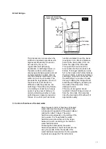
electronic panel 

control 

head 

overflow 

brine hose 

cover 

brine well 

brine valve 

anti-spill  

security 

salt tank 

well cover 

Fig. 1 

Summary of Contents for AQUAHOME 11-N

Page 1: ...AQUAHOME 11 N AQUAHOME 17 N Installation and operations manual Water softening station ENG ...

Page 2: ......

Page 3: ... activities 16 A Refilling salt in brine tank 16 B Salt bridges 17 C Control of hardness of treated water 17 D Control of water pressure in the installation 18 E Mechanical filter operation 18 F Control of current hour clock indications 18 2 Operational recommendations 19 3 Operation logbook 19 4 Troubleshooting table 19 Section IV 20 1 Technical specifications and dimensions 20 Chapter V 21 1 Con...

Page 4: ...inquire with the service team of your of the device Basic data Prior to connecting commissioning and operation of the device please fill in the following information MOD NO SER NO Information on model number and serial number can be found on the label accessible after lifting of the brine tank cover Commissioning date Water hardness dH German water hardness scale Water pressure bar 4 ...

Page 5: ...28 V Please use the transformer that is supplied together with the device To avoid defects resulting from power outage it is recommended to install a back up power supply In case of damage of the power cable the transformer must be immediately disconnected Prior to reconnecting the transformer damaged power cable must be replaced or repaired Prior to removing the outer valve cover power supply of ...

Page 6: ...r heater or boiler unit make sure that the temperature of water at the connection point does not exceed 49 0 C It is recommended that a check valve is fitted between the water softener and the water heater or boiler unit in order to prevent hot water backflow to the water softener Excessively hot water may cause damage of control valve elements as well as the ion exchange resin Make sure that the ...

Page 7: ... pipe located at the rear part of the control head and place the other end of the hose in the outlet drain fig 3 Make sure to provide at least 4 cm air gap between the end of the hose and the outlet drain This gap is needed to prevent backflow of sewer water into the water softener Install the hose in a manner preventing its movement during intense flow of washings The hose must be not be bent twi...

Page 8: ... program no part on the overflow hose can be placed above the outflow level fig 3 the overflow hose of the brine tank must not be connected to the outflow stub pipe of the control valve see point 1 above Fig 3 8 Treated water Fastening clamps Main water flow 3 4 connection pipe 3 4 joint 3 4 nut Copper pipe Seal Washings hose BY PASS VALVE Seal and nut Copper pipe 3 4 connection pipe 3 4 joint Har...

Page 9: ...vice team Audio signaller BIP the signaller will activate each time the button is pressed A single audio signal indicates one change on the display screen Series of audio signals indicate wrong button being pushed and the need to push a different button Setting Time If the PRESENT TIME information was not displayed it is necessary to press the OK button fig 4 until the information is displayed In ...

Page 10: ...centration exceeding 0 2 mg l please use adjusted water hardness instead of water hardness It is calculated in the following manner Adjusted hardness o dH hardness o dH 4 8 iron quantity in mg Fe l Enter the water hardness number or adjusted water hardness number expressed in gpg to the water softener software as operational water hardness In order to enter the water hardness number press and hold...

Page 11: ...ndation results from the possibility of formation of so called salt bridges fig 6 For premises with standard humidity the brine tank can be filled to full i e up to the level of the brine valve well height During normal operation of the device the control valve allows certain volume of water into the brine tank in order to generate aqueous salt solution that is later used for regeneration of the m...

Page 12: ... necessary to check the hardness of the output water If the hardness value is too high in relation to the desired value it is necessary to turn the knob in the opposite direction while holding the piston handle Once the desired hardness is set the water hardness adjusting knob may be locked in place by tightening the hex nut turning it clockwise until stop Make sure that each time the by pass valv...

Page 13: ...commissioning of the device Immediate regeneration Press the button fig 4 and hold it until the display screen shows a flashing caption reading RECHARGE NOW The first phase of the regeneration process will begin filling the brine tank with water Subsequent phases will be activated automatically Upon completion of the regeneration process the device s water softening capacity will be restored Regen...

Page 14: ...flashing 24 HR or 12 HR caption Setting the time mode 12 hour clock or 24 hour clock In order to change the 24 hour clock to 12 hour clock or vice versa press or to obtain the desired value Press the OK button Setting the backwash and fast rinse duration time The display screen will show the TIME caption as well as for example the flashing bA or 3 caption This means that the backwash duration time...

Page 15: ...ent time to return to the main screen D Power outage If electrical power to the water softener is lost the display screen will turn off but the microprocessor will keep all settings for several hours When electrical power is restored verify and reset the time if it is flashing or is incorrect The programmed values of the water hardness and the hour of the regeneration process s activation should n...

Page 16: ... notice Due to specific requirements concerning the quality of the regeneration agent only regeneration salt approved by the water softener manufacturer should be used regeneration salt in tablets A Refilling salt in brine tank The control of the level of salt in the tank is a basic maintenance activity during the use of the softener The activity should be carried out once a week If the tank is on...

Page 17: ...k before it strikes the tank bottom it will be most likely a salt bridge Push the broom stick into the salt bridge in a number of spots this way breaking the bridge Never break the salt bridge by pounding on the walls of the brine tank It may damage the tank If the use of wrong kind of salt resulted in the salt bridge remove it from the brine tank then carefully rinse the tank and refill it with s...

Page 18: ...mination is carried out by visual inspection An additional element enabling control of the filter condition is monitoring of water pressure upstream and downstream of the filter In case of using a filter with a replaceable cartridge provided that the cartridge is worn contaminated unscrew the filter sump holding the cartridge replace it with a new filter cartridge and tighten the sump with the new...

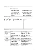
Page 19: ...er that is too hard or entirely unsoftened No salt in the tank Refill the salt Activate manual regeneration Power outage Restore power supply Check the displayed time Activate manual regeneration Occluded outflow of sewage from the valve Restore patency of the washings discharge hose Water softener supplies water salt level remains unchanged Salt bridge has been formed in the brine tank Remove the...

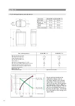
Page 20: ... 0 4 49 48 0 17 62 3 400 2 0 60 1 Regenerative salt Recommended salt types regenerative salt in tablets Dimensions AQUAHOME 11 N AQUAHOME 17 N A Total height 65 0 cm 82 2 cm B Height of water connections 52 3 cm 69 5 cm Depth Width 48 0 cm 30 0 cm 48 0 cm 30 2 cm Inlet outlet spacing 8 6 cm 8 6 cm 20 INLET OUTLET 8 6 cm 48 0 cm 30 2 cm Presented chart illustrates the relationship between the ion e...

Page 21: ... position 3 Check whether the water inlet and outlet hoses are properly connected to the inlet and outlet openings respectively 4 Check whether the transformer is properly connected to an earthed socket and whether the connection cable is properly fitted 5 Check whether the washings discharge hose is twisted or bent or whether it is arranged at the height below 2 40 metres over ground along its en...

Page 22: ...22 ...

Page 23: ...de labour costs and costs of an employee delegation and travel The supplier shall perform such warranty inspection in return for remuneration upon notification by the User on warranty inspection deadline The notification should be submitted in writing via fax email or regular mail or should be performed via telephone not later than 7 days prior to the deadline of the warranty inspection 5 The supp...

Page 24: ...ry out warranty inspections 7 4 self performance by the Purchaser or third parties of repairs alterations and modifications contrary to the warranty conditions off the Supplier Date of commissioning Date Signature and seal Certification of carried out inspections 1 warranty inspection date seal and signature 2 warranty inspection date seal and signature 3 warranty inspection date seal and signatur...

Page 25: ...he party carrying out the commissioning Full company name Address Tel E mail Device commissioned Information on model number and serial number can be found on the label accessible after lifting of the brine tank cover Mod No Ser No Raw water quality Hardness Iron Manganese Treated water quality Hardness Iron Manganese Remarks Supplementation Signature of the User Signature of the party carrying ou...

Page 26: ......

Page 27: ...me Address Tel E mail Device commissioned Information on model number and serial number can be found on the label accessible after lifting of the brine tank cover Mod No Ser No Raw water quality Hardness Iron Manganese Treated water quality Hardness Iron Manganese Remarks Supplementation Signature of the User Signature of the party carrying out the commissioning not required in case of tap water 2...

Page 28: ......

Page 29: ...Section VI 1 Component drawings 29 Head parts on a separate page ...

Page 30: ...11 7269508 Float and anti spill lock set Aquahome 11 N 7293395 Float and anti spill lock set Aquahome 17 N 12 7337490 Transformer 28V DC 13 7250826 Power feeder extension 14 7340265 Controller with display PWA 15 7294838 Top cover without a decal Decal 16 7266754 Control panel 17 7294846 Brine tank flap 18 7295054 Rim 19 7155115 Brine well cover 20 7106962 Brine well Aquahome 11 N 7263099 Brine we...

Page 31: ...31 Washer Seal Cross section view ...

Page 32: ...cabling 89 7337466 Head cover 90 7342657 Bolt 10 144 x 5cm 5 pcs 91 7327631 Bypass 3 4 7290957 Injector repair set includes items 76 80 82 86 Part No Part no Description 50 7338111 Bolt 6 199 x 3 3 5 cm required 2 51 7281291 Motor 52 7337474 Camshaft cover 53 7284964 Camshaft 54 7030713 Micro switch 7331185 Washings outflow connection set includes items 55 59 55 Washings nozzle clamp 56 Washings n...

Page 33: ... Inspection Act of 21 December 2000 Polish Journal of Laws no 122 item 1321 as well as the Regulation of the Minister of Economy Labour and Social Policy of 9 July 2003 Polish Journal of Laws no 135 item 1269 with amendments Article 15 paragraph 45 1 of the Act of 20 April 2004 on the amendment and repeal of certain laws due to obtaining membership in the European Union by the Republic of Poland P...

Reviews: