


In normal operation, the control shows that maintenance is due every
4320 operating hours (=180 operating days).
Display indication: [Perform maintenance]
The acoustic signal can be switched off by pressing the buttons T1
[Sound off] and T3. The display goes off after the maintenance has
completed.
There is a pressure switch in the lid of the Grundfix Plus Control which
issues the signal to close the motor-powered flap in case of back pres‐
sure. During cleaning work, the cover must not be cleaned with a high-
pressure cleaner, abrasive cleaning agents, blades or similar cleaning
equipment.
To avoid damage, only clean casing, flap mechanisms and seals with
soft brushes under running water.
The buttons should only be used if the lid is firmly screwed onto the
Grundfix Plus Control.
▶
Choose the menu [Maintenance] by pressing button T1 and con‐
firming with button T3.
INFO!
The display remains unchanged after bringing up the
[Maintenance] menu.
▶
Close the motor-powered flap by pressing the button T2.
▶
Set the emergency lock in
"
ZU
"
(OFF) position.
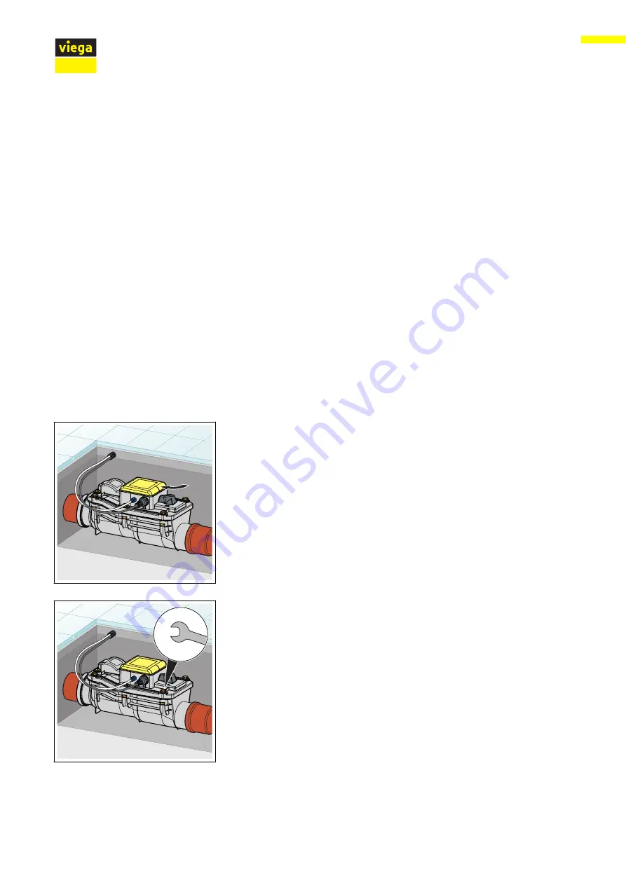
▶
Loosen the screws on the lid.
Y
Handling
Grundfix Plus Control backflow trap type 3
35