background image

Maintenance and Troubleshooting

52

Vidikron Vision Model 10/Model 12 Owner’s Operating Manual

PRE

L

IMINAR

Y

5.6 
Lamp Replacement

1.

Turn off the projector and wait for the cooling fan to stop. 

2.

Unplug the power cord. Allow the projector to cool down for approximately one hour 
prior to removing the lamp assembly for replacement.

3.

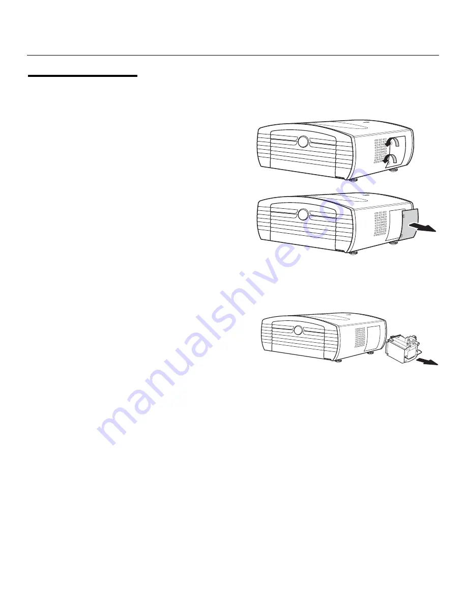
Loosen the two captive 
lamp cover screws and 
remove the cover.


4.

Loosen the four lamp 
assembly mounting screws.

5.

Grasp the lamp assembly 
handle and pull gently, 
removing the lamp module 
from the projector housing. 
As you do so, the lamp 
cooling interlock switch on 
the inside of the lamp cavity 
(near the top) moves to the 
OFF position. 


6.

Gently slide the new lamp assembly into the lamp cavity. Align the two power 
connectors at the top of the lamp assembly with the two sockets at the top of the lamp 
cavity. Press gently on both sides of the lamp assembly to snap it into place. As you do 
so, the lamp cooling interlock switch returns to the ON position.

7.

Tighten the lamp assembly mounting screws. 

8.

Replace the lamp cover and secure the captive lamp cover screws.

9.

Plug in the projector and turn it on. 

10. Reset the Lamp Timer to zero. To do this, select Lamp Timer Reset from the ISF 

Calibration menu and press 

ENTER

. The Vision 10/12 shows the number of hours the 

projector lamp has been in service and asks you to confirm or cancel the reset. Press 

ENTER

 again to confirm. 

Summary of Contents for DLP 40828

Page 1: ...10 12 DLP PROJECTORS VERSION 1 0 O W N E R S O P E R A T I N G M A N U A L...

Page 2: ......

Page 3: ...original warranty period This Limited Warranty only covers failure due to defects in materials and workmanship that occur during normal use and does not cover normal maintenance This Limited Warranty...

Page 4: ...is beyond normal operating distance of the closest Vidikron Authorized Service Center or the repair requires the unit be returned to the Vidikron factory it is the owner s responsibility to arrange fo...

Page 5: ...____ ________________________________________ Model Purchased Date ____________________________________________________________________________________________________________ Serial Number __________...

Page 6: ...9 The 12V trigger only outputs DC 12V signal for triggering Do not connect to any other power input or output This could cause damage to this unit 10 Only use accessories specified by Vidikron 11 Keep...

Page 7: ...efits 3 Key Features and Benefits 3 Parts List 4 2 Controls and Functions 5 Vision 10 12 at a Glance 5 Front Top Side View 5 Rear Top Side View 7 Vision 10 12 Remote Control 9 3 Installation 13 Remote...

Page 8: ...ientation 30 Lens Adjustments 31 Focus Zoom 31 Shift 32 Using the On Screen Menus 32 Main Menu 34 Source Select 34 Aspect Ratio 34 Picture Adjust 36 Image Option 42 Installation 44 ISF Setting 46 5 Ma...

Page 9: ...t Video Connections 26 3 11 Composite and S Video Connections 26 3 12 RS 232 Control System Connection 27 3 13 Connecting the 12 Volt Trigger Output 27 4 1 Adjusting the Feet 29 4 2 Focus and Zoom Con...

Page 10: ...List of Figures x Vidikron Vision Model 10 Model 12 Owner s Operating Manual P R E L I M I N A R Y...

Page 11: ...kron welcomes your comments about this manual Send them to info vidikron com Textual and Graphic Conventions Text Conventions The following conventions are used in this manual in order to clarify the...

Page 12: ...ecial significance They also provide supplemental information CAUTIONS alert users that a given action or omitted action can degrade performance or cause a malfunction WARNINGS appear when a given act...

Page 13: ...cement within virtually any home theater environment Among the finest attributes of the Vision 10 12 is its ability to meet the rigid Imaging Science Foundation ISF industry standards for video fideli...

Page 14: ...ed please contact your Vidikron dealer or Vidikron Customer Service at 888 4VIDIKRON Vision 10 Vision 12 DLP Projector Remote Control Unit and two 2 AAA size batteries HD 15 pin VGA to HD 15 pin VGA c...

Page 15: ...ual 5 P R E L I M I N A R Y 2 1 Vision 10 12 at a Glance Figure 2 1 and Figure 2 2 show the locations of key Vision 10 12 projector components Front Top Side View Figure 2 1 Vision 10 12 Top Front Sid...

Page 16: ...can be rotated to match the projector orientation inverted ceiling mounted or upright To rotate the logo grip it at the sides pull it away from the projector and rotate it 180 degrees 6 FRONT IR SENSO...

Page 17: ...Controls and Functions Vidikron Vision Model 10 Model 12 Owner s Operating Manual 7 P R E L I M I N A R Y Rear Top Side View Figure 2 2 Vision 10 12 Rear Top Side View 1 8 7 2 3 4 6 10 9 5...

Page 18: ...A connection to a personal computer The Vision 10 12 automatically detects the signal resolution 480i 480p 576i 720p or 1080i 5 DVI Computer Input Digital HDCP compliant digital video input for connec...

Page 19: ...er s Operating Manual 9 P R E L I M I N A R Y 2 2 Vision 10 12 Remote Control Figure 2 3 shows the Vision 10 12 remote control and the paragraphs that follow describe its functionality Figure 2 3 Visi...

Page 20: ...uttons ANA Anamorphic For viewing 16 9 DVDs or HDTV programs in their native aspect ratio 4X3 Standard 4 3 Scales the input signal to fit 4 3 display mode in the center of the screen L BOX Letterbox F...

Page 21: ...ettings for the current input from the Custom memory preset 12 ISF NIGHT Press to recall settings for the current input from the ISF Night memory preset 13 Cursor Keys Use these buttons to select item...

Page 22: ...Controls and Functions 12 Vidikron Vision Model 10 Model 12 Owner s Operating Manual P R E L I M I N A R Y Notes...

Page 23: ...e polarities correctly match the and markings inside the battery compartment 3 Insert the lower tab of the cover into the opening and press down the cover until it clicks in place Notes on Batteries W...

Page 24: ...or high temperature The remote control may malfunction under a fluorescent lamp If that occurs move the projector away from the fluorescent lamp Make sure that there is nothing obstructing the infrare...

Page 25: ...dure For Details refer to page 1 Choose a location for the projector 16 2 Connect signal sources to the projector 22 3 Connect external controller to RS 232 port optional 27 4 Apply power to the proje...

Page 26: ...e may cause drifts in the projector circuitry which may affect performance Keep the projector away from devices that radiate electromagnetic energy such as motors and transformers Common sources of th...

Page 27: ...has a lens throw ratio of between 1 40 and 1 60 The Vision 12 has a lens throw ratio of between 1 42 and 1 65 The result of this calculation tells you roughly how far back the projector should be pos...

Page 28: ...the projector and screen as shown in Figure 3 3 you can use the lens shift controls to center the image on the screen Lens shift is generally expressed as a percentage of the screen height or width as...

Page 29: ...I N A R Y Figure 3 5 Horizontal Lens Shift 0 Screen Center 100 Width Lens Shift 1 0 x W 50 Width Lens Shift 0 5 x W 150 Width Lens Shift 1 5 x W Screen Width W Note This is a general example of lens s...

Page 30: ...ng the on screen display OSD controls to compensate For detailed instructions refer to Using the On Screen Menus on page 32 Table 3 3 Vertical and Horizontal Lens Shift Limits Vision 10 Vision 12 Lens...

Page 31: ...moved during a presentation Ceiling Mounting The projector can also be inverted and suspended from the ceiling using a specially designed ceiling mount fixture This type of mounting is recommended for...

Page 32: ...t for connecting a DVD player DTV decoder personal computer or any other device with a DVI or HDMI output Connect such devices as shown in Figure 3 7 or Figure 3 8 Route all cables through the opening...

Page 33: ...Installation Vidikron Vision Model 10 Model 12 Owner s Operating Manual 23 P R E L I M I N A R Y Figure 3 7 DVI Source Connections DVD player or DTV decoder DVI D cable Desktop Computer DVI D cable...

Page 34: ...Installation 24 Vidikron Vision Model 10 Model 12 Owner s Operating Manual P R E L I M I N A R Y Figure 3 8 HDMI Source Connections DVD player or DTV decoder HDMI to DVI D cable not included...

Page 35: ...on 10 12 Use with signals other than those listed may cause some functions not to work 2 Some Macintosh computers may require a Macintosh video adapter Contact your nearest authorized service center o...

Page 36: ...ut connect it to the Vision 10 12 as shown in Figure 3 10 Figure 3 10 Component Video Connections Composite S Video Connections The Vision 10 12 has S Video and composite video inputs for connecting a...

Page 37: ...refer to Serial Communications on page 55 Figure 3 12 RS 232 Control System Connection Connecting to the 12 Volt Trigger Output If your home theater contains equipment that responds to a 12 volt trigg...

Page 38: ...Installation 28 Vidikron Vision Model 10 Model 12 Owner s Operating Manual P R E L I M I N A R Y Notes...

Page 39: ...12 will start projecting 4 2 Adjusting the Projector Height or Projection Angle When the Vision 10 12 is installed upright you can adjust the projector height or projection angle by turning the four...

Page 40: ...u 4 Press or to select the desired language The change takes effect immediately 4 4 Adjusting the Picture Orientation By default the Vision 10 12 is configured for a floor front installation in which...

Page 41: ...ocation of the focus and zoom controls Figure 4 3 shows the location of the lens shift controls Focus Zoom To focus the projected image rotate the focus ring left or right To make the picture larger z...

Page 42: ...SD position to access that menu 4 Use the up or down arrow buttons to select the setting you want to change 5 Press the right or left arrow button to change that setting OR With some settings you can...

Page 43: ...gs Custom 1 ISF Day ISF Night Source Select Video S Video Component 1 Component 2 RGB HD DVI Aspect Ratio Anamorphic 16 9 Standard 4 3 not available with HD signals LetterBox IntelliWide Cinema Cinema...

Page 44: ...and press ENTER Select the appropriate aspect ratio for the type of program material being viewed refer to Table 4 1 The currently selected aspect ratio is indicated by a green square Q to its left in...

Page 45: ...eo cassettes This aspect ratio is not available with HD signals LetterBox LET BOX In Letterbox mode the image is stretched vertically the top and bottom portions are blanked off Letterbox is best suit...

Page 46: ...o 3 Video 4 RGB HD 5 DVI Although it may be possible to obtain satisfactory picture quality using the naked eye and regular program material Vidikron recommends using the following calibration tools f...

Page 47: ...5 Typical PLUGE Pattern for Adjusting Brightness PLUGE patterns vary but generally consist of some combination of black white and gray areas against a black background The example above includes two...

Page 48: ...ing the left and right arrow buttons adjust the contrast to a point just below which the white rectangle starts to increase in size Color Saturation On your external test pattern source select a color...

Page 49: ...sed the image appears redder when it is increased the image appears greener To set the tint select Tint from the Picture Adjust menu While looking at the color bar pattern through a blue filter adjust...

Page 50: ...ottom Lower the sharpness setting to eliminate them Figure 4 8 Typical Test Pattern for Adjusting Sharpness Gamma The Gamma control determines how gray shades are displayed between minimum input black...

Page 51: ...hown in Figure 4 9 CIE stands for Commission Internationale de l clairage International Commission on Illumination the organization responsible for color measurement and management standards Changing...

Page 52: ...of the following settings to a preset otherwise they will be lost when a new input source or resolution is selected Aspect ratio Picture adjustments brightness contrast color saturation tint sharpness...

Page 53: ...outer edges and enlarges the remaining portion of the image to fill the display area Select from 0 to 10 of Overscan as desired For HDTV DVDs and other video sources Overscan is generally not necessa...

Page 54: ...us stay on screen when no buttons are pressed Select a time out period of 5 15 or 60 seconds OSD Transparent To allow the projected image to show through the OSD menus select OSD Transparent from the...

Page 55: ...ironment use Fan High Speed Mode to prevent it from overheating Set Fan High Speed Mode to ON to run the fan at high speed set it to OFF to run the fan at normal speed 1 The Vision 10 12 keystone corr...

Page 56: ...call at a later time You can create up to three presets designated Custom1 ISF Day and ISF Night per input and resolution You should save changes to any of the following settings to a preset otherwise...

Page 57: ...e color saturation level the amount of that color in a video image Lower settings produce less saturated colors a setting of 64 removes that color from the image entirely If the saturation is too high...

Page 58: ...idikron logo image stays on screen after you turn on the projector Select from 15 to 60 seconds in 5 second increments Noise Reduction To apply Digital Noise Reduction DNR to the input signal select N...

Page 59: ...t gently with a soft flannel cloth For hard to remove dirt soak a cloth in a neutral detergent diluted with water wring the cloth well and then wipe the projector Strong cleaning detergents may discol...

Page 60: ...g temperature You should periodically clean the vents by vacuuming them with a vacuum cleaner Vidikron recommends doing this after every 100 hours of use or more often if the projector is used in a di...

Page 61: ...es or deterioration of the lamp due to usage The period of time up to failure largely varies depending on the individual lamp and the condition and the frequency of use It is important to note that fa...

Page 62: ...e inside of the lamp cavity near the top moves to the OFF position 6 Gently slide the new lamp assembly into the lamp cavity Align the two power connectors at the top of the lamp assembly with the two...

Page 63: ...mbled DVD player is set to progressive scan mode Turn off progressive scan on the DVD player Connect the DVD player to the HD RGB 1 or HD RGB 2 input Image is too bright and or lacks definition in the...

Page 64: ...Maintenance and Troubleshooting 54 Vidikron Vision Model 10 Model 12 Owner s Operating Manual P R E L I M I N A R Y Notes...

Page 65: ...le 6 1 Serial Commands Command Description Reply RRA00 Saves current settings to the CUSTOM 1 memory Note 1 RRAOK RRA01 Saves current settings to the ISF Day memory Note 1 RRAOK RRA02 Saves current se...

Page 66: ...K PON Turns the projector ON Random Note 2 Table 6 1 Serial Commands continued Command Description Reply Notes 1 All image quality settings must be made with the remote control After the image adjustm...

Page 67: ...Width x 1 40 Maximum Screen Width x 1 60 Vision Model 12 Minimum Screen Width x 1 42 Maximum Screen Width x 1 65 Horizontal and Vertical Offset Vision Model 10 Horizontal 8 of screen width left or ri...

Page 68: ...htness for film based projectors using an open gate without film in the projector More importantly today SMPTE specifies 12 fL as the target image brightness in Digital Cinema theaters The foot Lamber...

Page 69: ...7 1 shows the Vision 10 12 dimensions Figure 7 1 Vision 10 12 Dimensions 398 0mm 181 8mm 162 6mm Rear View Side View Side View Bottom View Front View 429 4mm 431 6mm 22 8mm 164 6mm 87mm 87mm 164 6mm...

Page 70: ...Horizontal Frequency kHz Vertical Frequency Hz VESA Standard DVI Support Display PC VGA 640 x 350 27 0 60 Upscale 31 5 70 37 9 85 720 x 350 27 0 60 31 5 70 640 x 400 27 0 60 31 5 70 37 9 85 720 x 400...

Page 71: ...ompatibility Chart continued PC MAC WS Resolution Horizontal Frequency kHz Vertical Frequency Hz VESA Standard DVI Support Display Notes 1 This projector may not be able to display images from noteboo...

Page 72: ...ote 1 Comp 1 Comp 2 S Video Com posite VGA DVI SD Video NTSC 640 x 480i 15 73 59 94 60 PAL 768 x 576i 15 63 50 SECAM NTSC 4 43 adjustment required PAL M PAL N NTSC J PAL 60 NTSC 50 not supported EDTV...

Page 73: ......

Page 74: ...Vidikron 2900 Faber Street Union City CA 94587 510 324 5900 Fax 510 324 5905 1 888 4 VIDIKRON www vidikron com RUMA 011175 rev 11 28 05 v1 0 SERIAL NUMBER...

Reviews: