background image


74


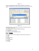
Figure 6-6  

5.2.16.2.1 

Preset Setup 

Note:

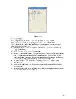
 The following setups are usually operated in the 

491H

Figure 6-2, 

492H

Figure 6-5 

and 

493H

Figure 6-6. 

In 

494H

Figure 6-2, use eight direction arrows to adjust camera to the proper position. 

In 

495H

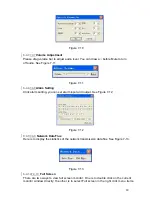
Figure 6-5, click preset button and input preset number. The interface is shown as 

in 

496H

Figure 6-7. 

Add this preset to one patrol number  


Figure 6-7  

5.2.26.2.2 

Activate Preset  

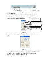
In 

497H

Figure 6-6 please input preset number in the No. blank, and click preset button. 

5.2.36.2.3 

Patrol Setup 

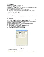
In 

498H

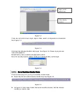
Figure 6-5, click patrol button. The interface is shown as in 

499H

Figure 6-8. 

Input preset number and then add this preset to one patrol. 


Figure 6-8  

5.2.46.2.4 

Activate Patrol 

In 

500H

Figure 6-6, input patrol number in the No. blank and click patrol button  

5.2.56.2.5 

Pattern Setup 

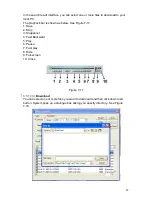
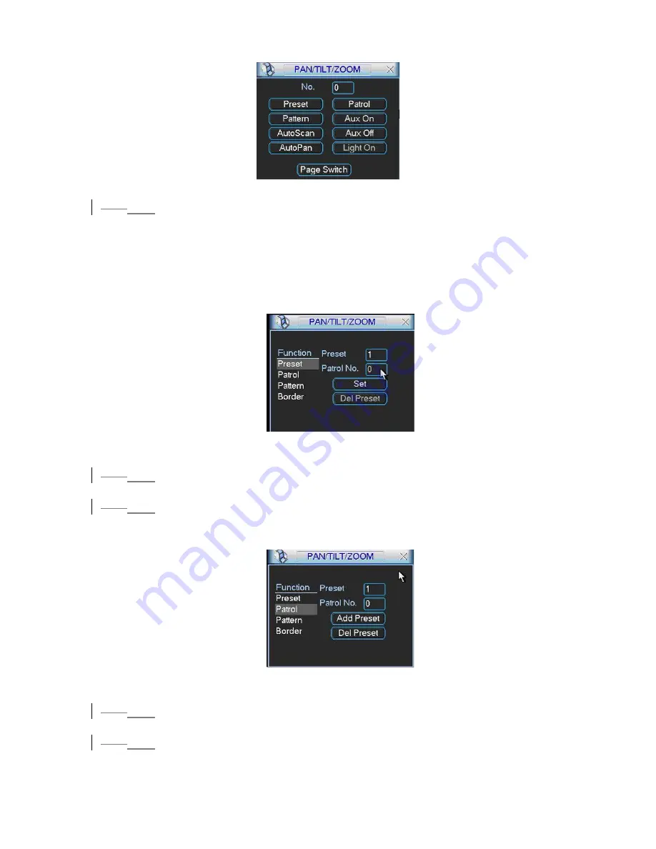
In 

501H

Figure 6-5, click pattern button and then click begin button. The interface shows 

like 

502H

Figure 6-9. 

Summary of Contents for LNS series

Page 1: ...1 LNS series Standalone DVR User s Manual ...

Page 2: ...Connection Sample 188H16 8H2 3 Remote Control 189H17 9H2 4 Mouse Control 190H18 10H2 5 Virtual Keyboard Front Panel 191H19 11H2 5 1 Virtual Keyboard 192H19 12H2 5 2 Front Panel 193H19 13H3 INSTALLATION AND CONNECTIONS 194H20 14H3 1 Check Unpacked DVR 195H20 15H3 2 HDD Installation 196H20 16H3 2 1 Choose HDDs 197H20 17H3 2 2 Calculate HDD Size 198H20 18H3 2 3 HDD Installation 199H20 19H3 3 CD DVD B...

Page 3: ...25 30H3 7 3 Matrix Video Output 211H25 31H3 7 4 Alarm Input and Relay Output 212H25 32H3 7 5 Alarm Input 213H25 33H3 7 6 Alarm Output 214H26 34H3 7 7 Alarm Input and Output Details 215H26 35H3 7 8 Relay Output Description 216H27 36H3 8 RS232 217H29 37H3 9 RS485 218H29 38H3 10 Other Interfaces 219H30 39H4 OVERVIEW OF NAVIGATION AND CONTROLS 220H31 40H4 1 Login Logout Main Menu 221H31 41H4 1 1 Login...

Page 4: ...Go to alarm setup interface 243H43 63H4 6 2 Alarm setup 244H43 64H4 7 Backup 245H44 65H4 7 1 Detect Device 246H44 66H4 7 1 Backup 247H44 67H4 8 PTZ Control and Color Setup 248H45 68H4 8 1 Cable Connection 249H45 69H4 8 2 PTZ Setup 250H45 70H4 8 3 3D Intelligent Positioning Key 251H47 71H4 9 Preset Patrol Pattern Scan 252H47 72H4 9 1Preset Setup 253H48 73H4 9 2 Activate Preset 254H48 74H4 9 3 Patro...

Page 5: ...Display 274H60 94H5 3 10 Default 275H61 95H5 4 Search 276H61 96H5 5 Advanced 277H61 97H5 5 1 Hard Disk Management 278H62 98H5 5 2 Alarm Output 279H63 99H5 5 3 Alarm Input 280H63 100H5 5 4 Manual Record 281H63 101H5 5 5 Account 282H63 102H5 5 6 Auto Maintain 283H64 103H5 5 7 TV Adjust 284H65 104H5 5 8 Video Matrix For DVR 1604LNH S Series Only 285H65 105H5 6 Information 286H69 106H5 6 1 Hard Disk I...

Page 6: ...unction 304H75 124H6 3 Dome Menu Control 305H75 125H7 WEB CLIENT OPERATION 306H76 126H7 1 Network connection 307H76 127H7 2 Login and logout 308H76 128H7 3 Go to Real time Monitor Mode 309H77 129H7 4 Video Right Mouse Menu Operation 310H78 130H7 4 1 Real time Monitor 311H78 131H7 4 2 Multi camera Preview 312H78 132H7 4 3 Start Dialog 313H78 133H7 4 4 Decode Quality 314H78 134H7 4 5 Playback Contro...

Page 7: ...r Manage 335H90 155H7 7 2 Record Control 336H93 156H7 7 3 Log Information 337H93 157H7 7 4 Date and Time 338H94 158H7 7 5 System Information 339H94 159H7 7 6 Alarm Prompt 340H94 160H7 7 7 Channel Name 341H95 161H7 7 8 Upgrade BIOS 342H95 162H7 7 9 Reboot 343H96 163H7 7 10 Matrix Applies for some special series only 344H96 164H7 7 11 About 345H96 165H7 7 12 Mail 346H96 166H7 8 Un install Web Contro...

Page 8: ...ction 354H101 174H9 2 Keyboard 355H101 175H10 FAQ 356H102 176HAPPENDIX A HDD CAPACITY CALCULATION 357H104 177HAPPENDIX B COMPATIBLE USB DRIVE LIST 358H105 178HAPPENDIX C COMPATIBLE CD DVD BURNER LIST 359H106 179HAPPENDIX E COMPATIBLE SATA HDD LIST 360H107 ...

Page 9: ...ed to be a reference tool for the installation and operation of your system Here you can find information about this series DVR features and functions as well as a detailed menu tree Before installation and operation please read the following safeguards and warnings carefully ...

Page 10: ... are nor liable for any problems caused by unauthorized modifications or attempted repair 5 Environment The DVR should be installed in a cool dry place away from direct sunlight inflammable explosive substances and etc 6 Accessories Be sure to use all the accessories recommended by manufacturer Before installation please open the package and check all the components listed below are included z One...

Page 11: ...th Dahua Speed Dome 3D intelligent positioning function supported z Easy backup methods USB devices CD RW DVD RW network download z Alarm triggering screen tips buzzer PTZ preset matrix output e mail FTP upload z Smart HDDs Management non working HDD hibernation HDD faulty alarm Raid function z Powerful network software built in web server multi DVR client CMS Networking access for remote live vie...

Page 12: ...n detection recording TV Output Adjustment Adjust TV output color display zone Audio Only LNS 16H with audio Audio Input 4 channel BNC 200 2800mV 30KΩ Bidirectional Talk Input 1 channel BNC 200 2800mV 30KΩ Audio Output 1 channel BNC 200 3000mv 5KΩ Audio Compression ADPCM Video Detection Alarm Motion Detection Zones 192 16 12 detection zones Sensitivity 1 6 level 6 is highest Trigger recording PTZ ...

Page 13: ...zoom into full screen during playback Backup Mode Flash stick USB HDD USB CD RW DVD RW built in SATA Burner network download Network Interface RJ 45 Port 10 100M Network Functions TCP IP DHCP DDNS PPPoE E mail FTP Remote operation Monitor PTZ control playback system setting file download log information Auxiliary Interface USB Interface 2 ports 1 for mouse control 1 for backup RS232 DAHUA keyboard...

Page 14: ...gure 2 1 S N Name Icon Function 1 Power button POWER Power button Press this button for three seconds to shut down DVR 2 Record indication light When DVR is recording this indication light turns on 3 USB port Connect to USB mouse or USB backup devices 4 Remote control receiver To receive remote control signal 5 Power indication light When connect to power this indication light turns on Please inse...

Page 15: ...15 1 42 2 Rear Panel 1 4 12 2 1Overview Please refer to 362HFigure 2 3 for real panel information Figure 2 3 ...

Page 16: ...ample Here is a connection sample for your reference See 363HFigure 2 4 Figure 2 4 Model LNS 04 08 16 LNS 16H Audio Input NO 4 channel Loop Output NO 16 channel Matrix Output NO 1 channel Bidirectional NO 1 channel Audio Input ...

Page 17: ... shown next Figure 2 5 Serial Number Function 1 remote switch 2 Multiple window switch 3 0 9 number key 4 Record 5 Auxiliary key 6 Confirm menu key 7 Cancel 8 Direction key 9 forward 10 Previous 11 Back 12 Next 13 Slow play 14 Stop 15 Fast play 16 Play Pause ...

Page 18: ... for backspace button stands for space button In English input mode _stands for input a backspace icon and stands for deleting the previous character In numeral input mode _ stands for clear and stands for deleting the previous numeral When input special sign you can click corresponding numeral in the front panel to input For example click numeral 1 you can input or you can click the numeral in th...

Page 19: ... the check box Page up or page down Move mouse Select current control or move control Drag mouse Select motion detection zone Select privacy mask zone 1 72 5 Virtual Keyboard Front Panel 1 7 12 5 1Virtual Keyboard The system supports two input methods numeral input and English character small and capitalized input Move the cursor to the text column the text is shown as blue input button pops up on...

Page 20: ...t to HDD capacity You can use 120G 750G HDD to guarantee higher stability The formula of total HDD size is Total Capacity MB Camera Amount Recording Hours HDD Usage Per Hour M h H 264 compression is ideal for standalone DVRs It can save more than 30 HDD capacity than MPEG4 When you calculate the total HD capacity you should estimate the average HDD capacity per hour for each channel For example fo...

Page 21: ... and screw firmly After HDD installation please check connection of data ribbon and power cord Note For LN SATA series the HDD ports are SATA and there is no need to set master slave HDD 2 33 3 CD DVD Burner Installation For USB burners you need to install USB series burner This series DVR is compatible with various burner brands popular in today s market You can consult our local technical suppor...

Page 22: ...We recommend you use UPS to guarantee steady operation DVR life span and other peripheral equipments operation such as cameras 2 63 6 Connecting Video Input and Output Devices 2 6 13 6 1Connecting Video Input The DVR automatically detects the video standard PAL or NTSC whenever you connect a video input It accepts both color and black and white and analog video NOTE z Enabling line lock on cameras...

Page 23: ...onitor the DVR can automatically detects the monitor type And without any output device by default the DVR is configured to use a TV monitor In this case if your application requires a VGA monitor you have to press the button FN or Shift on the front panel or restart the DVR NOTE Video output 1 and VGA can t display at the same time But Video output 2 can display properly with Video Output 1 or VG...

Page 24: ...o inputs I bidirectional audio input 1 audio output Audio input bidirectional audio input and audio output The DVR encodes audio and video signals simultaneously which lets you control audio at the monitored location To set up audio 1 Make sure your audio input device matches the RCA input level If the device and RCA input levels do not match audio distortion problems may occur 2 Make sure the aud...

Page 25: ...r to the video matrix output connector 2 Turn the DVR on the monitor and each video matrix output source 3 Verify the video from each source and troubleshoot as necessary Please refer to 368HFigure 3 5 Figure 3 5 2 7 43 7 4Alarm Input and Relay Output The DVR offers 16 alarm inputs for external signaling devices such as door contacts or motion detectors Each alarm input can be either normally open...

Page 26: ...rmation Figure 3 7 2 7 73 7 7 Alarm Input and Output Details You can refer to the following sheet and 371HFigure 3 8 for alarm input and output information Parameter Grounding Alarm Ground Ground line Alarm Input 1 2 16 Relay Output 1 2 3 4 NO and C Normally Open and Com 5 NO C and NC Normally Open Com Normally Closed 6 Ctrl 12V This is used for reset the senor 485 A B 485 communication port They ...

Page 27: ...o the DVR alarm input ALARM z If you need to reset the touched off alarm remotely you can use DVR to supply controllable 12 V power to the alarm detector such as the smoke detector z Use the same ground with that of DVR if you use external power to the alarm device Figure 3 9 2 7 83 7 8 Relay Output Description z 6 ways relay alarm output Provide external power to external alarm device z To avoid ...

Page 28: ...del JRC 27F Material of the touch Silver Rating resistance load Rated switch capacity 30VDC 2A 125VAC 1A Maximum switch power 125VA 160W Maximum switch voltage 250VAC 220VDC Maximum switch currency 1A Insulation between touches with same polarity 1000VAC 1minute between touches with different polarity 1000VAC 1minute ...

Page 29: ... 1 Assemble the KBD keyboard according to the instructions in its accompanying installation manual 2 Connect the KBD keyboard into one of the RS232 ports on the DVR or through network 2 93 9 RS485 When the DVR receives a camera control command it transmits that command up the coaxial cable to the PTZ device RS485 is a single direction protocol the PTZ device can t return any data to the unit To en...

Page 30: ...30 2 103 10 Other Interfaces There are still other interfaces on the DVR such as USB ports You can refer to the 375HFigure 3 12 for more information Figure 3 12 ...

Page 31: ...ds 666666 Lower authority user who can only monitor playback backup and etc z Username default Password default hidden user For your system security please modify you password after first login You can use USB mouse front panel remote controller or keyboard to input About input method Click to switch between numeral English character small capitalized and denotation Note 3 times login failure with...

Page 32: ... status after power failure 3 1 54 1 5Replace Button Battery Please make sure to use the same battery model if possible We recommend replace battery regularly such as one year to guarantee system time accuracy 3 24 2 Recording Operation 3 2 14 2 1 Live Viewing When you login the system is in live viewing mode You can see system date time and channel name If you want to change system date and time ...

Page 33: ...here are three statuses schedule manual stop Highlight icon to select corresponding channel z Manual the highest priority After manual setup all selected channels will begin ordinary recording z Schedule channel records as you have set in recording setup Main Menu Setting Schedule z Stop all channels stop recording Figure 4 5 3 2 2 34 2 2 3 Enable disable record Please check current channel status...

Page 34: ...ord Please highlight ALL after Manual See 383HFigure 4 8 When system is in manual recording all scheduled set up you have set in will be null Main menu Setting Schedule You can see indication light in front panel turns on system begins manual record now Figure 4 8 3 2 2 54 2 2 5 Stop all channel recording Please highlight ALL after Stop See 384HFigure 4 9 System stops all channel recording no matt...

Page 35: ...ng file z A external alarm recording file z M motion detection recording file z C card and pos test overlay recording file For some special series only There are several playback windows This System supports 1 ch playback Figure 4 10 Please refer to the following sheet for more information Serial Number Function 1 Play 2 Backward 3 Stop 4 Slow play 5 Fast play 6 Previous frame 7 Next frame 8 Volum...

Page 36: ...ure 4 10 3 3 2 64 3 2 6 Slow playback and fast playback Please refer to the following sheet for slow play and fast playback function Button Illustration Remarks Fast play button In playback mode click this button to switch between various fast play modes such as fast play 1 fast play 2 and more Fast play 1 means fast play level 1 or not about speed Frame rate may vary due to different versions Slo...

Page 37: ...layback Double click backward play button again system goes to pause mode When system is in backward play or frame by frame playback mode you can click play button to go to normal playback Manual playback frame by frame Click pause button in normal playback mode slowly turn the jog inner dial clock wise to view frame by frame counter clock wise to view I frame playback Note All the operations here...

Page 38: ...nable this function please set at least one HDD as redundant Refer to the manual for detailed information z Prerecord System supports prerecord function The previous one to three seconds video before alarm occurs can be included in recorded video z Record types There are three types regular motion detection MD and Alarm Please highlight icon to select the corresponding function After all the setup...

Page 39: ...support file search function so you need to set at least one read write disk otherwise you can not record video Note About redundancy setup please note z If current channel is not recording current setup gets activated when the channel begin recording the next time z If current channel is recording now current setup will get activated right away the current file will be packet and form a file then...

Page 40: ...value ranges from 10 300 Unit second z PTZ preset Click set button the interface is shown as in 396HFigure 4 15 Here you can set preset for one or more channels z Region click select button to set motion detection region See 397HFigure 4 16 z Sensitivity there are six levels The six level is of the highest sensitivity z Alarm output when alarm occurred system enables peripheral alarm devices z Sho...

Page 41: ... Alarm output activate peripheral alarm device when video loss occurred z Enable tour Here is for you to activate tour between different cameras z Latch when motion detection completes system auto delays detecting for a specified time The value ranges from 10 300 Unit second z PTZ preset Click set button to set preset for one or all channels See 401HFigure 4 16 z Period 1 2 It is for you to set tw...

Page 42: ...different cameras z Latch when motion detection completes system auto delays detecting for a specified time The value ranges from 10 300 Unit second z PTZ preset Click set button to set preset for one or all channels See 403HFigure 4 16 z Period 1 2 there are for you to set two periods 00 00 24 00 z Alarm output when camera masking occurred system enables peripheral alarm devices Please highlight ...

Page 43: ...time you need to set alarm record in schedule interface Main Menu Setting Schedule and select schedule record in manual record interface Main Menu Advance Manual Record z Latch Here is for you to set proper delay duration Value ranges from 10 to 300 seconds System automatically delays specified seconds in turning off alarm and activated output after external alarm cancelled z PTZ preset Here is fo...

Page 44: ...and end time Click add button system begins search All matched files are listed below System automatically calculates the capacity needed and remained See 407HFigure 4 21 system only backup files with a before channel name You can use Fn or cancel button to delete after file serial number Click backup button you can backup selected files There is a process bar for you reference When the system com...

Page 45: ... system only save the previous 5 minute data in the device The file name format usually is SN_CH channel number time Y M D H M S In the file name the YDM format is the same as you set in general interface Main Menu Setting General You can visit our website to view listed CD ROM type 3 84 8 PTZ Control and Color Setup Note All the operation here is based on DH SD protocol For PELCO protocols there ...

Page 46: ...s 9600 z Data bits select corresponding data bits Default value is 8 z Stop bits select corresponding stop bits Default value is 1 z Parity there are three options odd even none Default setup is none Figure 4 23 After all the setting please click save button In one window display mode right click mouse click Fn Button in the front panel or click Fn key in the remote control The interface is shown ...

Page 47: ...e 4 27 Click this key system goes back to the single screen mode Drag the mouse in the screen to adjust section size It can realize PTZ automatically Figure 4 27 Here is a sheet for you reference Name Function key function Shortcut key Function key function Shortcut Key Zoom Near Far Focus Near _ Far Iris close W Open f 3 94 9 Preset Patrol Pattern Scan In 415HFigure 4 25 click the set button The ...

Page 48: ...ure 4 25 use eight direction arrows to adjust camera to the proper position In 423HFigure 4 28 click preset button and input preset number The interface is shown as in 424HFigure 4 30 Now you can add this preset to one patrol tour Figure 4 30 4 9 2 Activate Preset In 425HFigure 4 29 please input preset number in the No blank and click preset button 4 9 3 Patrol Setup Tour setup In 426HFigure 4 28 ...

Page 49: ... Go back to 432HFigure 4 32 and click end button You can memorize all these operations as pattern 1 Figure 4 32 4 9 6 Activate Pattern Function In 433HFigure 4 29 input mode value in the No blank and click pattern button 4 9 7 Auto Scan Setup In 434HFigure 4 28 click border button The interface is shown as in 435HFigure 4 23 Please go to 436HFigure 4 25 use direction arrows to select camera left l...

Page 50: ...ges to stop button Click stop button to terminate scan operation 3 104 10 Dome Menu Control In 439HFigure 4 29 click page switch button the interface is shown as below See 440HFigure 4 34 Click menu to enter dome menu The direction arrows here are to control dome menu Click page switch button system goes back to 441HFigure 4 25 Figure 4 34 ...

Page 51: ...R menu tree is shown as below 4 25 2 Main Menu When you login the system main menu shows as below See 442HFigure 5 1 There are totally six icons search Information setting backup advanced and shutdown Move the cursor to highlight the icon then double click mouse to enter the sub menu ...

Page 52: ...z Date separator there are three denotations to separate date dot beeline and solidus z Time format there are two types 24 hour mode or 12 hour mode z Language system supports various languages Chinese simplified Chinese Traditional English Italian Japanese French Spanish All languages listed here are optional Slight difference maybe found in various series z HDD full Here is for you to select wor...

Page 53: ... select from the dropdown list z Resolution System supports various resolutions you can select from the dropdown list For this series we can support CIF z Bit rate system supports two types CBR and VBR z Quality There are six levels ranging from 1 to 6 Level six is the highest image quality z Frame rate there are six levels 1 f s 2f s 3f s 6f s 12f s 25f s Some series DVRs only support PAL 25f s z...

Page 54: ...you to select z Baud rate You can select proper baud rate z Data bit You can select proper data bit z Stop bit There are three values 1 1 5 2 z Parity there are three choices none odd even After all the setups please click save button system goes back to the previous menu Figure 5 5 4 3 55 3 5Network Here is for you to input network information See 447HFigure 5 6 z IP address z Subnet mask z Gatew...

Page 55: ...rties There are three options for you FTP NTP Alarm center You can select corresponding ways and then click properties button to go to setup interface z Authorization Click authorization button please highlight icon to enable IP authentication function When you enable this function only IP in the list can login this DVR See 448HFigure 5 7 After all the setups please click save button system goes b...

Page 56: ...rk DDNS input your PPPoE name you get from you IPS and server IP PC with DDNS Click save button and then reboot system Click save button system prompts for rebooting to get all setup activated After rebooting open IE and input as below http DDNS server IP virtual directory name webtest htm e g http 10 6 2 85 DVR _DDNS webtest htm Now you can open DDNSServer web search page 4 3 5 35 3 5 3 FTP You n...

Page 57: ... the following interface See 453HFigure 5 10 Figure 5 10 Please highlight the icon in front of Enable to activate FTP function Now FTP can upload alarm video and motion detection video Please note when you are using this function please make sure current upload channel is in motion detection or alarm record status and there is video available Here you can input FTP server address port and etc ...

Page 58: ... and period 2 you can set two periods for one each channel System file name is shown as in 454H Figure 5 12 Figure 5 12 4 3 5 45 3 5 4 NTP You need to install SNTP server Such as Absolute Time Server in your PC first In Windows XP OS you can use command net start w32time to boot up NTP service In 455HFigure 5 6 select NTP and then click properties button You can see the following interface See 456...

Page 59: ... refer to chapter 4 5 Detect 4 3 85 3 8Pan Tilt Zoom The pan tilt zoom setup includes the following items Please select channel first See 457HFigure 5 14 z Protocol select corresponding PTZ protocol such as DH SD1 z Address input corresponding PTZ address z Baud rate select baud rate z Data bit select data bit z Stop bit select stop bit z Parity there are three choices none odd even After all the ...

Page 60: ...z Channel display You can select channel name or not z Overlay information System displays some information in the screen for your reference z Enable tour activate tour function z Interval Input proper interval value here The value ranges from 5 200 seconds In tour process you can use mouse or click Shift to turn on window switch function Stands for opening switch function stands for closing switc...

Page 61: ...l the setups please click save button system goes back to the previous menu Warning System menu color language time display mode video format IP address user account will not maintain previous setup after default operation Figure 5 16 4 45 4 Search Please refer to chapter 4 3 Search 4 55 5 Advanced Double click advanced icon in the main window the interface is shown as below See 460HFigure 5 17 Th...

Page 62: ... you can refer to chapter 4 4 Schedule After all the setups please click save button system needs to reboot to get all the modification activated Figure 5 18 Click alarm set button the interface is shown as below See 462HFigure 5 19 Please highlight icon to select the corresponding function You can enable one or more alarm setups The lower limit ranges from 1 to 99 Alarm channel number ranges from...

Page 63: ...re 5 20 4 5 35 5 3Alarm Input Here is for you to set alarm input Please highlight icon to select the corresponding input channel After all the setups please click save button system goes back to the previous menu See 464HFigure 5 21 Figure 5 21 4 5 45 5 4Manual Record Please refer to chapter 4 2 2 manual record 4 5 55 5 5Account Here is for you to implement account management See 465HFigure 5 22 H...

Page 64: ...n not be deleted When there is no login user hidden user default automatically login You can set some rights such as monitor for this user so that you can view some channel view without login z One user should belong to one group User right can not exceed group right z About reusable function this function allows multiple users use the same account to login After all the setups please click save b...

Page 65: ...devices such as TV walls analog matrix and so on 4 5 8 25 5 8 2 Matrix outputs They are like the small scale matrix You can select any camera from our DVR to switch And the output can also tour between the cameras So the matrix outputs can be used to build TV walls and tour and display the cameras one by one 4 5 8 35 5 8 3 Rear Panel Connection The rear panel is shown as below See 468HFigure 5 25 ...

Page 66: ...atrix See 470HFigure 5 27 Figure 5 27 4 5 8 5 25 5 8 5 2 Right mouse menu In one window display mode right click mouse to select Video Matrix See 471HFigure 5 28 Figure 5 28 4 5 8 65 5 8 6 Video Matrix Interface and Application LNH S series support 1 channel matrix outputs The video matrix interface is shown as in 472HFigure 5 29 ...

Page 67: ...there is no alarm activation tour 4 5 8 6 25 5 8 6 2 Alarm Tour Select the alarm in channel number from the dropdown list If there is an alarm signal from the channel selected the matrix output will go to tour as you set in the Alarm setting Main Menu Setting Alarm See 473HFigure 5 30 Alarm tour has higher priority than single tour during this period the single tour will stop After alarm activatio...

Page 68: ...of the DVR Matrix output 2 tours between CAM1 CAM6 and CAM7 of the DVR The interval is five seconds Figure 5 31 4 5 8 7 25 5 8 7 2 Example two In 475HFigure 5 32 when alarm occurs in channel one the activated matrix output one begins touring between CAM1 CAM3 and CAM4 of the DVR until alarm activation tour stops Figure 5 32 ...

Page 69: ...d status See 477HFigure 5 34 Note Please remove the broken hard disk before you add a new one Once there is a hard disk confliction please check hard disk time and system time is the same or not Please go to setting then general to modify system time At last reboot the system to solve this problem In IDE information column means OK X means error occurred means there is no disk The serial number af...

Page 70: ...8HFigure 5 35 Figure 5 35 4 6 35 6 3Log Here is for you to view system log file System lists the following information See 479HFigure 5 36 Figure 5 36 4 6 45 6 4Version Here is for you to view some version information See 480HFigure 5 37 z Channel z Alarm in z Alarm out z System version z Baud rate z Start upgrade ...

Page 71: ...oper system right Figure 5 38 4 75 7 Exit Double click exit button system pop up a dialogue box for you to select See 482HFigure 5 39 z Logout menu user log out menu You need to input password when you login the next time z Restart application reboot DVR z Shutdown system shuts down and turns off power z Restart system system begins rebooting Figure 5 39 ...

Page 72: ... See 483HFigure 6 1 Figure 6 1 Click Pan Tilt Zoom the interface is shown as in 484HFigure 6 2 Here you can set the following items z Zoom z Focus z Iris Click icon and to adjust zoom focus and Iris Figure 6 2 In 485HFigure 6 2 please click direction arrows See 486HFigure 6 3 to adjust PTZ position There are totally eight direction arrows Please note there are only four direction arrows in DVR fro...

Page 73: ... function Shortcut key Function key function Shortcut key Zoom Near Far Focus Near _ Far Iris close W Open f 5 26 2 Preset Patrol Pattern Border Function In 488HFigure 6 2 click the set button The interface is shown as below Here you can set the following items z Preset z Patrol z Pattern z Border Figure 6 5 In 489HFigure 6 2 click page switch button you can see an interface as in 490HFigure 6 6 H...

Page 74: ... one patrol number Figure 6 7 5 2 26 2 2Activate Preset In 497HFigure 6 6 please input preset number in the No blank and click preset button 5 2 36 2 3Patrol Setup In 498HFigure 6 5 click patrol button The interface is shown as in 499HFigure 6 8 Input preset number and then add this preset to one patrol Figure 6 8 5 2 46 2 4Activate Patrol In 500HFigure 6 6 input patrol number in the No blank and ...

Page 75: ...to select camera left limit and then please go to 509HFigure 6 10 and click left limit button Repeat the above procedures to set right limit Figure 6 10 5 2 86 2 8Activate Border Function In 510HFigure 6 6 click auto scan button the system begins auto scan Correspondingly the auto scan button changes to stop button Click stop button to terminate scan operation 5 36 3 Dome Menu Control In 511HFigur...

Page 76: ...network z Use order ping DVR IP address to check connection is OK or not Usually the return TTL value should be less than 255 6 27 2 Login and logout Open IE and input DVR address in the address column For example if your DVR IP is 10 1 27 200 then please input http 10 1 27 200 in IE address column System pops up warning information to ask you whether install webrec cab control or not Please click...

Page 77: ... is admin and password is admin Note For security reasons please modify your password after you first login Figure 7 4 6 37 3 Go to Real time Monitor Mode There are three ways for you to go to real time monitor mode z Select the channel number besides function key See 518HFigure 7 5 Figure 7 5 z In 519HFigure 7 5 click video button then select real time monitor click the channel number you want to...

Page 78: ...title protocol for DVR z Volume adjustment here is for you to adjust PC audio volume z Alarm setting here is for you to set alarm input and alarm output z Network data flux here is for you to view current data flux z Full screen enter into full screen display mode z Video zoom there are four options 20 40 60 80 100 z Video windows Support 1 2 4 window display mode Figure 7 6 6 4 17 4 1Real time Mo...

Page 79: ...utton in 523HFigure 7 8 The interface is shown as below See 524HFigure 7 9 Figure 7 9 Here is for you to control direction operation There are eight levels ranging from 1 to 8 Level 8 is the fastest speed In 525HFigure 7 9 click PTZ set button You can see the following dialogue box See 526HFigure 7 10 You can select in the dropdown list SIT is 3D positioning button Around SIT are eight PTZ directi...

Page 80: ...tting you can set alarm input and output See 528HFigure 7 12 Figure 7 12 6 4 97 4 9 Network Data Flux Here is to display the statistics of the network transmission data flux See 529HFigure 7 13 Figure 7 13 6 4 107 4 10 Full Screen There are two ways to view full screen monitor One is to double click on the current monitor window directly the other is to select Full screen in the right click menu i...

Page 81: ...o Windows Here is for you to choose display mode See 531HFigure 7 15 Figure 7 15 6 57 5 Search Here you can select video type channel number and time to search the file you want Click search button the interface is shown as below See 532HFigure 7 16 Please use page up down key to view the search results Double click file name you can view the file and system will automatically backup the image in ...

Page 82: ...as below See 533HFigure 7 17 1 Save 2 Stop 3 Snapshoot 4 Fast Backward 5 Play 6 Pause 7 Fast play 8 Hide 9 Full screen 10 Close Figure 7 17 6 5 17 5 1Download You can select one or more files you want to download and then click down load button System pops up a dialogue box asking you specify directory See 534HFigure 7 18 ...

Page 83: ...le name is usually made up of file name Channel N date time File extension name is dav For example file name a 0120021205071028 mp4 means z 01 channel 1 z 20021205 5th December 2002 z 071028 7 o clock 10 minutes 28 seconds 6 67 6 Configure Click configure button there are totally seven function keys See 536HFigure 7 20 z Image z Alarm z Motion detection z Network z Video parameter z General z Sche...

Page 84: ...nt configuration to a directory The file extension name is CFG See 538HFigure 7 21 Figure 7 21 6 6 1 27 6 1 2 Load configuration Click import configuration button in 539HFigure 7 20 You can draw a before checkbox to load you previously backup file See 540HFigure 7 22 Click Ok button and then select file of extension name CFG Now you have updated system setup ...

Page 85: ...or stop recording when disk is full You can select channel number protocol address and baud rate to control the lens or PTZ Figure 7 23 6 6 37 6 3Schedule Click schedule button the interface is shown as in 542HFigure 7 24 Here you can draw a before Sunday to Saturday And then set various time periods from 0 to 24 o clock You can draw a to enable record type record motion alarm ...

Page 86: ...BR z Quality There are six levels The different data flux occupies different bandwidth and the transmission image qualities are also different Among them level 6 needs the widest bandwidth and can reveal the best image quality Please note you setup here only applies for image quality in web or client end z Resolution there are several resolutions for you You can select from the dropdown list z Ala...

Page 87: ... for you to choose record channel and output port See 544HFigure 7 26 There are two alarm types normal open or normal close Delay time ranges from 10 to 300 seconds You can draw a before the check box to enable record camera and output port ...

Page 88: ...on detection area Click Full screen or right click mouse to view the motion detection area in full screen After setting the area you can Save channel or Clear the area Alarm output Here you can enable alarm output channel Please draw a before the check box Please note if you want to set this channel as motion detection recording you need to turn off the schedule recording setup for this channel Ma...

Page 89: ...e s current IP Now you can visit this IP camera via this IP d Visit via DNS You need a PC of fixed IP in the internet and there is the DDNS software running in this PC In other words this PC is a DNS domain name server In network DDNS input your PPPoE name you get from you IPS and server IP PC with DDNS Click save and then reboot system Click save button system prompts for rebooting to get all set...

Page 90: ...nels setup you can click save at the button to save all configurations Figure 7 30 6 77 7 Assistant Click assistant setting the interface is shown as below See 550HFigure 7 31 There are nine function keys Please note Matrix control item only applies for some special series Figure 7 31 6 7 17 7 1User Manage Here is for you to manage users and user groups See 551HFigure 7 32 You can click to see the...

Page 91: ...ation 6 7 1 27 7 1 2 Delete Group Click Delete Group button the interface is shown as in 553HFigure 7 34 Note You can only delete empty group E g There is no user in current group Figure 7 34 6 7 1 37 7 1 3 Modify Group Click modify group the interface is shown as in 554HFigure 7 35 You can modify group name and then click power button to set proper right for the whole group Figure 7 35 ...

Page 92: ...gure 7 33 557HFigure 7 36 click power button the interface is shown as in 558HFigure 7 37 Here is for you to set user s power There are three power groups main control power monitor power playback power You can draw a before the checkbox to enable corresponding function Figure 7 37 6 7 1 67 7 1 6 Modify user Select one user and then click modify user button the interface is shown as in 559HFigure ...

Page 93: ...button the interface is shown as below See 561HFigure 7 40 You can select mode for each channel Figure 7 40 6 7 37 7 3Log Information System can automatically backup all operation in log information You can click this button to view detailed information See 562HFigure 7 41 Once you click save log button the log files will be automatically saved in the root directory such as C as a text file e g C ...

Page 94: ... system See 564HFigure 7 43 Here you can z Turn on off audio z Select video type z Select preview image z Preview image z Close or open auto tour monitoring z View network data flux Figure 7 43 6 7 67 7 6Alarm Prompt Here is for you to choose different alarm audios See 565HFigure 7 44 Here you can select system AlarmSound wav file from folder system32 as your audio sound ...

Page 95: ...ou modify channel name in DVR end this modification not applies to web end or standalone end you need to use this interface to refresh Figure 7 45 6 7 87 7 8Upgrade BIOS Click upgrade BIOS button the interface is shown as below See 567HFigure 7 46 Open the BIOS file You can get from our local engineer or download from our web service and then click send BIOS button During the upgrade process there...

Page 96: ...ix control interface is shown as in 569HFigure 7 48 Figure 7 48 This feature is not available in LN S model 6 7 117 7 11 About Here is for you to view basic system information See 570HFigure 7 49 Figure 7 49 6 7 127 7 12 Mail In the assistant setup select email function You can see the interface is shown as in 571HFigure 7 50 Here you can input server IP receiver email title and etc ...

Page 97: ...ace For external alarm you can enable email function in alarm setup interface See 572HFigure 7 51 Figure 7 51 After setup you can receive email form client end The email content is shown as below Alarm Matter Email Test AlarmIn Channel 255 Alarm Start Date Day Month Year Hour Minute Second 12 12 2006 16 30 20 Alarm Device Name localhost ...

Page 98: ... Detect AlarmIn Channel 2 Alarm Start Date Day Month Year Hour Minute Second 12 12 2006 15 5 36 Alarm Device Name localhost Mail_Sender IP 10 6 3 9 6 87 8 Un install Web Control There are three ways for you to un install web control z From start click run and then input order regsvr32 u WebRec ocx z Use web un install tool uninstall web bat to un install web control ...

Page 99: ...vice upgrade simultaneously z E map and network backup support 7 28 2 Environment We recommend the following configuration Hardware z CPU P4 2 0G z Display card support hardware zoom such as ATI TNT2 PRO We recommend ATI9800 or above dual channel 128M 128bit z Network card 100M Software z For client end we recommend Windows 2000 or Windows XP 7 38 3 Overview Multiple client main window is shown as...

Page 100: ... window four window six window eight window nine window sixteen window z Section 4 Here is for you to view current help information z Section 5 Here is to display data flux and CPU status z Section 6 There are four function buttons PTZ Color setting Device Plan 7 48 4 More Details Please refer to the Professional Surveillance System User s Manual for more information ...

Page 101: ...2 Keyboard Control keyboard is very convenient for multi DVR control menu options and PTZ control Select keyboard control from system Setting RS232 Function and then set concerning attributes such as protocol Connect DVR RS232 port to shifter 25 pin RS232 port and then set proper control addresses for all connected DVRs Now you can input DVR control address and use keyboard keys to set menu or con...

Page 102: ...e dry and clean Keep ventilation openings smooth Otherwise it will reduce system stability and lifelong 6 I can not see video signal on one channel while the other channels are ok Check the video cable connection You can connect camera video cable directly to monitor to test If there is still no signal there may be a problem with camera or video cable If there is a video signal please contact your...

Page 103: ...normal 12 What peripheral equipment DVR can work with DVR supports much peripheral equipment such as keyboard matrix control decode card alarm input and output equipment alarm server and access control system Slight difference may be found in user interface All the designs and software here are subject to change without prior written notice Please visit our website for more information ...

Page 104: ...e capacity i m which is storage of each channel needed unit Mbyte i m i q i h i D 2 In the formula i h means the recording time for each day hour i D means number of days for which the video shall be kept Step 3 According to Formula 3 to calculate total capacity accumulation T q that is needed for all channels in the DVR during scheduled video recording c i i T m q 1 3 In the formula c means total...

Page 105: ... Freedom 1G Sandisk Cruzer Freedom 2G Kingston DataTraveler Ⅱ 1G Kingston DataTraveler Ⅱ 2G Kingston DataTraveler 1G Kingston DataTraveler 2G Maxell USB Flash Stick 128M Maxell USB Flash Stick 256M Maxell USB Flash Stick 512M Maxell USB Flash Stick 1G Maxell USB Flash Stick 2G Kingmax Super Stick 128M Kingmax Super Stick 256M Kingmax Super Stick 512M Kingmax Super Stick 1G Kingmax Super Stick 2G N...

Page 106: ...Interface Type Sony DRU 835A IDE DVD RW Sony DW Q120A IDE DVD RW Sony DW G120A IDE DVD RW Sony CRX 230AE IDE CD RW Sony CRX 320A IDE CD RW Sony CRX 225E IDE CD RW BenQ DW2000 IDE DVD RW BenQ DW1670 IDE DVD RW BenQ DW1650 IDE DVD RW BenQ DW1640 IDE DVD RW BenQ 5232W IDE CD RW Samsung TS H652M IDE DVD RW Sony AW G170S SATA DVD RW Samsung TS H653A SATA DVD RW Panasonic SW 9588 C SATA DVD RW Sony DRX ...

Page 107: ...ST3750330AS 750G SATA Seagate Barracuda 11 ST3500320AS 500G SATA Maxtor DiamondMax 20 STM3320820AS 320G SATA Maxtor DiamondMax 20 STM3250820AS 250G SATA Maxtor DiamondMax 21 STM3160211AS 160G SATA Maxtor DiamondMax 21 STM380211AS 80G SATA Maxtor DiamondMax 21 STM340211AS 40G SATA Western Digital Cariar SE WD3200JD 320G SATA Western Digital Cariar SE WD3000JD 300G SATA Western Digital Cariar SE WD2...

Reviews: