


3
T: +44 (0)1293 541 200
E: [email protected]
W: www.Videosys.tv
The information contained in this document is the property of Videosys Broadcast Ltd. This document and the
information contained herein is provided for evaluation purposes only and is subject to change without notice.
Videosys Broadcast Ltd assumes no responsibility for errors that might appear in this document and gives no
representations or warranties as to the accuracy of the information contained herein, including but not limited to
the suitability and performances of the product or its intended application.
© Copyright Videosys Broadcast Limited 2018. All Rights Reserved. (Version 3)
Your Camera Control Outdoor Unit
Getting Started
You will find the necessary information to connect
and operate the ODU within this manual and our
additional specific quick setup guides, if however,
additional support is required
please don’t hesitate to
contact your local distributor.
Introduction
The Videosys camera control system allows the user
to replace the cables between the Remote-Control
Panels, Camera Control Units and Cameras with a
robust broadcast quality wireless link.
The Videosys camera control solution consists of
three distinct components; an Indoor Unit (IDU) an
Outdoor Unit (ODU)and a camera Receiver Unit (RX).
Multiples of these components can be used to
construct larger scale setups, for example multiple
ODUs can be used to increase RF coverage forming a
‘cell
-
like’ infrastructure
Each camera to be controlled requires its own
receiver unit (RX).
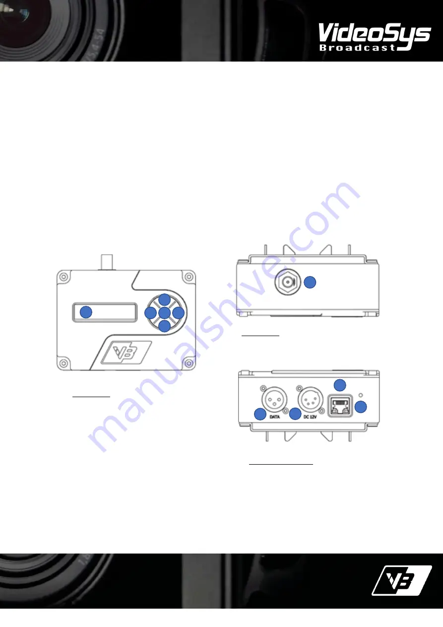
Front Panel
1.
OLED Display
2.
Left Button
3.
Up Button
4.
Right Button
5.
Down Button
6.
Enter Button
Connectors
7. TNC transmit antenna connector
Bottom Connectors
8. Data Input Connector (3 Pin XLR, Male)
9. Power Input Connector (4 Pin XLR, Male)
10. Ethernet Connector (RJ45)
11. RX signal indicator light
7
8
9
7
10
11
1
2
3
4
3
5
6


