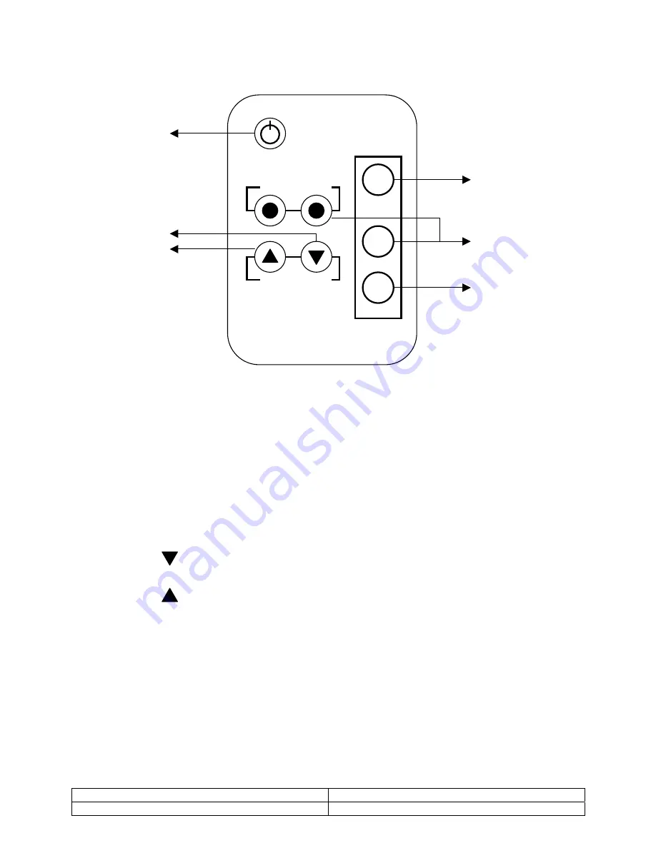
Videology 45M20-1 User Manual Download Page 12


12.  Remote Control 


Video       Audio 

 Up          Down 

Item 


Menu 


Source

1

4

2

5

3

6

1.  Power 

Monitor power ON / OFF. At OFF mode, monitor will be on standby status 
LED - Green Light -- Power On 
         Red Light    -- Standby mode 


2.  Adjust  

 Decrease the value on the OSD menu or turn ON / OFF function  
 

3.  Adjust 

Increase the value on the OSD menu or turn ON / OFF function 


4.  Item 

Choose sub menu from Video 

Press again to enter selected option 
 

5.  Menu 

NC 

 
6.  Source 

NC 


Doc # INS-45M20-1 

Issue Date: 10/08/08 

Revision: A 

Page 12 of 13 


Summary of Contents for 45M20-1

Page 1: ... make sure that they have the most recent manual version Videology holds no responsibility for any errors that may appear in this document Doc INS 45M20 1 Issue Date 10 08 08 Revision A Page 1 of 13 Videology Imaging Solutions Inc USA 37M Lark Industrial Parkway Greenville RI 02828 Tel 401 949 5332 Fax 401 949 5276 Videology Imaging Solutions B V Europe Liessentstraat 2B NL 5405 AG Uden The Nether...

Page 2: ...5 1 Control 5 6 Connectors 6 6 1 20 Monitor Back Panel 6 7 OSD Architecture 7 7 1 20 Monitor Video Function 7 8 LCD Monitor Mounting Guide 8 8 1 Desktop Mount 8 8 2 Wall VESA mount 8 9 Device Connectors 9 10 Specifications 10 11 Appendixes 11 11 1 Troubleshooting 11 11 2 Package Contents 11 12 Remote Control 12 13 Contact 13 Doc INS 45M20 1 Issue Date 10 08 08 Revision A Page 2 of 13 ...

Page 3: ...ecked by the qualified personnel before operating it any further Unplug the unit from the wall outlet if it is not going to be used for several days or more To disconnect the cord pull it out by the plug Never pull the cord itself Allow adequate air circulation to prevent internal heat built up Do not place the unit on surfaces rugs blankets etc or near materials curtains draperies that may block ...

Page 4: ...d by turning the equipment off and on the user is encouraged to try to correct the interference by one or more of the following measures Reorient or relocate the receiving antenna Increase the separation between the equipment and receiver Connect the equipment into an outlet on a circuit different from that to which the receiver is connected Consult the dealer or an experienced radio TV technician...

Page 5: ... and Horizontal Wall Mountable 5 Operating Instructions 5 1 Control 1 2 3 4 Figure 1 20 LCD Monitor 1 Power Monitor power ON OFF At OFF mode monitor will be at standby status Green Light Power On Red Light Standby mode 2 Adjust Increase the value on the OSD menu or turn ON OFF function 3 Adjust Decrease the value on the OSD menu or turn ON OFF function 4 Item Choose sub menu from Video Press again...

Page 6: ...nitor Back Panel 1 Regulated 12VDC Power Input 2 Video 1 IN Composite signal input for Video 1 3 Video 1 OUT Video looping output for Video 1 Figure 1 20 Back Panel Doc INS 45M20 1 Issue Date 10 08 08 Revision A Page 6 of 13 ...

Page 7: ...light or dark areas of the picture Brightness Adjusts the overall picture shade and brightness Tip Use the Brightness to make details in the dark areas of the picture to be just visible and Contrast to brighten the picture without causing video noise and foreheads to turn white Color Adds color to the black and white picture content of a color signal and is usually set for viewer s preference in c...

Page 8: ...LCD to fit the most comfortable monitoring status Figure 3 8 2 Wall VESA mount Please follow the fix hole size on back panel to install the LCD to the wall directly or use a VESA mount Wall Mounts VESA Mount Figure 4 Doc INS 45M20 1 Issue Date 10 08 08 Revision A Page 8 of 13 ...

Page 9: ...ce Figure 5 LCD Connectors a Connect External device such as DVD or Game Player to Monitor as shown in the above picture b Connect CCD Camera 1 and 2 to Monitor through Video Input 1 and 2 BNC Connect as showing in the above picture Doc INS 45M20 1 Issue Date 10 08 08 Revision A Page 9 of 13 ...

Page 10: ... p 75ohm Video Output 1 CH composite video 1Vp p 75ohm In Out Impedance Auto termination 75 Ohms Power Source 12VDC 90 260VAC 60Hz 50Hz adaptor Power Consumption 3 5A 45W Environmental Ambient Operating Temperature 10 C 50 C 14 F 122 F Operating Humidity 20 80 RH Mechanical Dimensions W x H x D 19 29 x 15 28 x 3 15 491mm x 388mm x 81mm Weight 7 kg 15 43 lbs Accessories Included Power supply power ...

Page 11: ...Abnormal line 6 Ghost image 7 Desired video disappears Checking Power not connected or not engaged Change to correct input channel Check signal cable Any interference from other devices Adjust video control on OSD Adjust video 11 2 Package Contents A LCD monitor B IR remote control C Power cord D User manual E 12V Power Adapter Revision A Page 11 of 13 ...

Page 12: ...us LED Green Light Power On Red Light Standby mode 2 Adjust Decrease the value on the OSD menu or turn ON OFF function 3 Adjust Increase the value on the OSD menu or turn ON OFF function 4 Item Choose sub menu from Video Press again to enter selected option 5 Menu NC 6 Source NC Doc INS 45M20 1 Issue Date 10 08 08 Revision A Page 12 of 13 ...

Page 13: ...Please note that data in this application note is subject to change without notification Videology Imaging Solutions Inc is an ISO 9001 registered video camera developer and manufacturer serving security industrial and machine vision biometric and specialty OEM markets The main facility is based in Greenville Rhode Island USA and Videology Imaging Solutions BV is located in Uden The Netherlands Th...

Reviews: