


12. DCV751 Motionviewer
XXVIII
.
Enrolling a DCV751 Motionviewer
AREAS AND
DEVICES
KEYPAD DISPLAY
to AREAS AND DEVICES
Then press
DEVICES then PRESS
ADD A NEW DEVICE Press
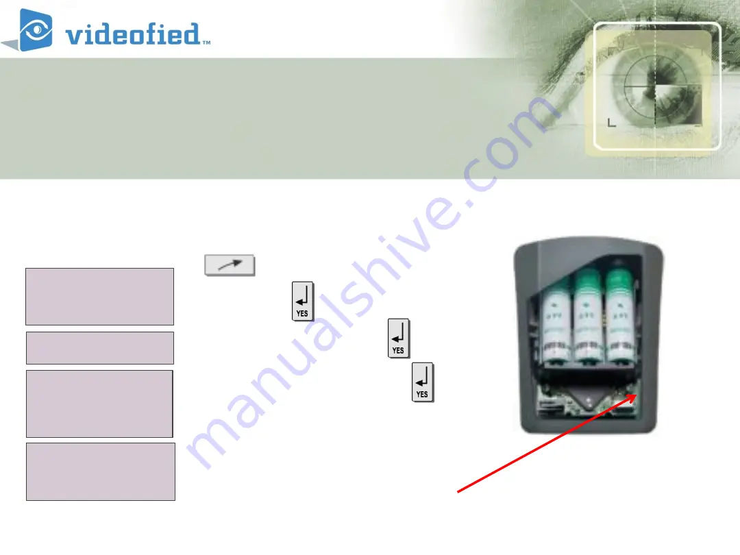
Insert the batteries
Press the program
– sync button
of device as per installation
sheet of device
DEVICES
ADD A NEW
DEVICE
PRESS PROGRAM
BUTTON OF DEVICE
Summary of Contents for XL 3.1
Page 1: ...Videofied XL Programming Module 3 1 ...
Page 5: ...Videofied XL Panel ...


