video xtreme VX-3000 Installation & Operation Manual Download Page 59

Installation

VX-3000 Installation/Operation Manual

45 

PRE

L

IMINAR

Y

Cylindrical Anamorphic 
Lens Installation and 
Adjustment

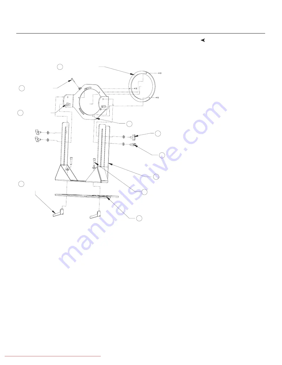
The Cylindrical Anamorphic lens mount kit consists of everything shown in Figure 3-20. 
Some components shipped with your projector may differ slightly from what is shown in 
these instructions. 

Figure 3-20. Cylindrical Anamorphic Lens Mounting Assembly - Exploded View

Attaching Lens Mounting Assembly to Lens Motor Carriage Plate or Fixed 
CineWide Base Plate: 

1.

Remove the two Yaw/X Adjustment Levers (item #8) from the bottom of the 
Anamorphic Lens Holder (item #5).

2.

Place the Anamorphic Lens Holder on top of the AutoScope Carriage Plate or Fixed 
CineWide Base Plate (item #7). Position the bracket so that the long slot at the bottom 
of the lens holder is perpendicular to the corresponding slots on the plate.

3.

Secure the Anamorphic Lens Holder to the plate using the Hex Bolts/Washers 
(item #6) and Yaw/X Adjustment Levers that you removed in Step 1. 

4.

Use the Lens Mounting Screws to attach the Lens Adapter Ring (item #1) to the Pitch 
Adjustment Yoke (item #2); see Figure 3-21. (Use the round, threaded holes on the 
yoke.)


2

3

4

6

7

8

5

1

9

Pitch Adjustment Yoke for Lens

Height/Y Adjustment
T-Screw and Washer 
(2x) 

T-Screw and 
Washer (2x)

Pitch Adjustment 

Anamorphic Lens
Holder 

1/4-20 Hex Bolt (2x)
and Washer (2x)

AutoScope Carriage Plate or 
Fixed CineWide Base Plate

Yaw/X Adjustment 
Lever (2x)

Lens Adapter Ring and
Mounting Screws (3x)

Pitch Adjustment 
T-Nut (2x)

10

Anamorphic Lens
Set Screw

Downloaded From projector-manual.com Runco Manuals

Summary of Contents for VX-3000

Page 1: ...1080p DLPTM Home Theater Projector INSTALLATION OPERATION MANUAL VX 3000 Downloaded From projector manual com Runco Manuals...

Page 2: ...Downloaded From projector manual com Runco Manuals...

Page 3: ...irst from the effective date of delivery to the initial end user Such replacement parts are then subsequently warranted for the remaining portion if any of the original warranty period This Limited Wa...

Page 4: ...the date of delivery to the end user For your convenience keep the original bill of sale as evidence of the purchase date Repairs made under the terms of this Limited Warranty covering your VX 3000 P...

Page 5: ...Limited Warranty please call or write RUNCO INTERNATIONAL LLC 1195 NW Compton Drive Beaverton OR 97006 1992 Ph 503 748 5799 Fax 503 748 8161 Toll Free 800 23 RUNCO 800 237 8626 PRODUCT INFORMATION RET...

Page 6: ...d use caution when moving the cart apparatus to avoid injury from tip over 13 Unplug this apparatus during lightning storms or when unused for long periods of time 14 Refer all servicing to qualified...

Page 7: ...ibility EMC Part 4 Testing and measurement techniques Section 6 Conducted disturbances induced by radio frequency fields immunity test EN 61000 4 8 Electromagnetic compatibility EMC Part 4 Testing and...

Page 8: ...nts of tin lead and or mercury Disposal of these materials may be regulated due to environmental considerations Lamp s inside this product contain mercury This product may contain other electronic was...

Page 9: ...a Glance 5 VX 3000 Rear Panel 8 VX 3000 Remote Control 9 3 Installation 13 Remote Control 13 Notes on Batteries 13 Notes on Remote Control Operation 13 Quick Setup 14 Installation Considerations 15 I...

Page 10: ...2 Primary Lens Adjustments 43 Focus and Zoom 43 Focus and Zoom VX 3000 Ultra 43 Lens Shift 43 Changing the OSD Language 43 Adjusting the Picture Orientation 44 Installing and Adjusting the CineWide An...

Page 11: ...ction and Port Configuration 77 Serial Command Syntax 77 7 Specifications 87 VX 3000 Specifications 87 Overall Dimensions VX 3000i CineWide and VX 3000d CineWide 90 Overall Dimensions VX 3000 Ultra 91...

Page 12: ...Table of Contents xii VX 3000 Installation Operation Manual P R E L I M I N A R Y Downloaded From projector manual com Runco Manuals...

Page 13: ...ase Plate and Ceiling Mounting Plate Exploded View 33 3 12 VX 3000 Ultra CineWide with Rainier II McKinley Cylindrical Lens Base Plate and Ceil ing Mounting Plate Exploded View 34 3 13 HDMI DVI Source...

Page 14: ...ncushion Correction 65 4 8 Gain and Offset 69 4 9 CIE 1931 Chromaticity Diagram 71 7 1 Overall Dimensions VX 3000i CineWide and VX 3000d CineWide Prismatic Lens 90 7 2 Overall Dimensions VX 3000 Ultra...

Page 15: ...ns Text Conventions The following conventions are used in this manual in order to clarify the information and instructions provided Remote and built in keypad button identifiers are set in upper case...

Page 16: ...supplemental information CAUTIONS alert users that a given action or omitted action can degrade performance or cause a malfunction WARNINGS appear when a given action or omitted action can result in d...

Page 17: ...nce Foundation ISF standards for maximum home theater image quality Runco s sophisticated parameters for white balance and color gamut control have also been implemented for precise balance of gray sc...

Page 18: ...ent of the light path through the optics enabling the perfect balance of black and white levels for each individual installation Parts List Your VX 3000 is shipped with the following items If any item...

Page 19: ...gure 2 2 show the key VX 3000 components Figure 2 1 VX 3000 Front Side Top View 1 EXHAUST VENT 2 ZOOM TAB Standard VX 3000 Use this to change the projected image size with a standard VX 3000 3 TOP IR...

Page 20: ...ation Flashes orange for approximately 110 seconds after the projector is turned off to indicate that the lamp is cooling down Red when an internal failure requiring service has occurred 7 LAMP LED In...

Page 21: ...t the sides pull it away from the projector and rotate it 180 degrees 2 CABLE OPENING Pass cables through this opening 3 CABLE ACCESS DOOR Open to access connectors 4 LAMP MODULE COVER Remove this cov...

Page 22: ...connecting a DVD HD DVD BD player HD set top box or other SD HD source 4 COMPOSITE VIDEO INPUT Standard composite video input for connecting a VCR laser disc player or other composite video source 5 S...

Page 23: ...YPbPr SD or HD video signals The VX 3000 automatically detects the signal format 2 3 VX 3000 Remote Control Figure 2 4 shows the VX 3000 remote control and the paragraphs that follow describe its fun...

Page 24: ...ent 2 RGB input HDMI HDMI 2 Press to select an HDMI input 4 INFO Displays active source signal resolution aspect ratio and other projector status information Cursor Keys Use these buttons to select it...

Page 25: ...Custom 2 memory preset 7 Aspect Ratio Selection Buttons Use these buttons to select an aspect ratio directly as follows 16 9 For viewing 16 9 DVDs or HDTV programs in their native aspect ratio 4 3 Sca...

Page 26: ...mode PIP Press to activate PIP mode PIP Press to enlarge the PIP window PIP Press to shrink the size of the PIP window 10 Motorized Lens Controls FOCUS VX 3000 Ultra only Press to focus the image ZOOM...

Page 27: ...remove the batteries to avoid damage from battery leakage Notes on Remote Control Operation Make sure that there is nothing obstructing the infrared beam between the remote control and the IR receiver...

Page 28: ...the projector 36 5 Connect signal sources to the VX 3000 37 6 Connect external controller to RS 232 port optional 40 7 Connect 12 volt trigger output to AutoScope lens motor or other equipment option...

Page 29: ...Installation Options Advantages Considerations Front Screen Floor Mount Installation Easy to set up Can be moved or changed quickly Easy to access Shares floor space with audience Front Screen Inverte...

Page 30: ...large enough to fill the screen Figure 3 1 Estimating Throw Distance Table 3 3 gives the throw ratios for the VX 3000 Table 3 3 Throw Ratios for the VX 3000 Projector Model Throw Ratio with Primary L...

Page 31: ...AutoScope McKinley Lens 1 87 2 20 135 76 159 72 1 40 1 65 134 40 158 40 Table 3 3 Throw Ratios for the VX 3000 continued Projector Model Throw Ratio with Primary Lens Only Throw Range in inches with...

Page 32: ...ift LENS controls on the projector remote to center the image on the screen Lens shift is generally expressed as a percentage of the screen height or width as shown in Figure 3 3 and Figure 3 4 Figure...

Page 33: ...s Shift Example Only 0 Screen Center 100 Width Lens Shift 1 0 x W 50 Width Lens Shift 0 5 x W Screen Width W Note This is a general example of lens shift Lenses vary in their shift capabilities No par...

Page 34: ...t Limits in Inches with a 100 by 56 inch 1 78 1 Screen Vertical Up 19 60 10 08 11 20 11 20 11 20 11 20 Down 28 00 14 00 24 64 24 64 25 76 25 76 Horizontal Left 0 10 00 Note 4 10 00 Right 0 10 00 Note...

Page 35: ...5 Folded Optics Other Considerations Other considerations and tips that can help improve your installation Keep the ambient temperature constant and below 35 C 95 F Keep the projector away from heati...

Page 36: ...eed as follows to install it 1 Carefully remove the projector from the shipping container and place it on a flat surface 2 Loosen the Phillips screw at the bottom of the decorative bezel on the front...

Page 37: ...cut and remove the plastic band around the lens motor connector wires Take great care not to cut the wires 7 Detach the lens motor connector from the motor by removing the two screws holding it in pl...

Page 38: ...s a male socket connector 9 Remove the front cap from the lens 10 Connect the lens motor to the projector 11 Hold the lens assembly with the motor facing upward Carefully insert the back of the lens a...

Page 39: ...e with the three Allen screws on the outer ring of the assembly using a 3 mm hex driver 14 Install the foam shield around the front of the lens 15 Replace the front lens bezel 16 Tighten the Phillips...

Page 40: ...pped with a cylindrical Rainier II or McKinley anamorphic lens proceed with Installing the Fixed CineWide Base Plate Cylindrical Lens page 33 If you are installing a VX 3000i CineWide with AutoScope V...

Page 41: ...ope or VX 3000d CineWide with AutoScope Motor Assembly Exploded View 4 5 Screw Phillips Pan Head 10 32 x 1 2 4x 1 AutoScope Lens Motor 2 Screw Phillips Flat Head 10 32 x 1 4 2x 3 CineWide with AutoSco...

Page 42: ...surface Then remove the two height adjusters at the front of the projector by turning them counterclockwise until they come out Standoff 10mm x 5mm x M5 Aluminum Black Anodize 4x 4 5 Screw Phillips P...

Page 43: ...and around the AutoScope lens motor housing For floor installations where the projector is upright the adapters allow the projector to lie flat on the mounting surface Using the four 4 supplied M6 x 1...

Page 44: ...the motor to the projector with the four 4 supplied 10 32 Pan Head Phillips screws item 1 and nylon spacers or aluminum standoffs item 7 4 Secure the AutoScope Ceiling Mount Adapters Projector Stands...

Page 45: ...projector ceiling mount kit with those on the bottom of the projector 3 Line up the two mounting holes on the CineWide base plate with those on the bottom of the projector and at the front of the ceil...

Page 46: ...ashers under Lens Base Plate 2 places Washers between Lens Base Plate and Ceiling Mounting Plate 2 places VX 3000i CineWide or VX 3000d CineWide with Prismatic Lens Base Plate VX 3000i CineWide or VX...

Page 47: ...mbly for a VX 3000i CineWide or VX 3000d CineWide Figure 3 11 VX 3000i CineWide or VX 3000d CineWide with Rainier II McKinley Cylindrical Lens Base Plate and Ceiling Mounting Plate Exploded View Ceili...

Page 48: ...se plate assembly Figure 3 12 VX 3000 Ultra CineWide with Rainier II McKinley Cylindrical Lens Base Plate and Ceiling Mounting Plate Exploded View Ceiling Mount Plate part of Ceiling Mount Kit Anamorp...

Page 49: ...e 3 12 4 If you are mounting the projector on a ceiling Line up the four holes on the projector ceiling mounting plate included with the projector ceiling mount kit with those on the bottom of the pro...

Page 50: ...ber crutch tips or turntable feet Adjusting the Projector Height or Projection Angle If the screen is significantly higher or lower than the projector you can also tilt the projector at a slight angle...

Page 51: ...use the included HDMI to HDMI cable with a DVI source use a DVI to HDMI cable Figure 3 13 HDMI DVI Source Connections Use the HDMI input whenever possible This ensures the highest video quality becau...

Page 52: ...pe connector Figure 3 14 RGB Connections Progressive Component Video Connections Connect your progressive component source DVD player or HD set top box to the COMP 2 RGB input as shown in Figure 3 15...

Page 53: ...ponent Video Connections Connect your composite S Video and component video sources to the VX 3000 as shown in Figure 3 16 Figure 3 16 Composite S Video and Component Video Connections S VID S VID DTV...

Page 54: ...about using this connection refer to Serial Communications on page 77 Figure 3 17 RS 232 Control System Connection S VID S VID 1 2 3 4 5 7 8 9 6 D Sub 9 pin female RJ 11 Male Communication Cable RJ 1...

Page 55: ...igure 3 18 Figure 3 18 Connecting the 12 Volt Trigger Output to the AutoScope Lens Motor If your home theater contains a retractable screen screen mask or other 12 volt trigger activated equipment con...

Page 56: ...r 1 Turn on your source components 2 If this is an AutoScope equipped projector turn on the main power switch at the rear of the AutoScope lens motor The lens motor power switch is located next to the...

Page 57: ...t and right arrow buttons to adjust the focus To make the picture smaller zoom out press the ZOOM button then use the left arrow button To enlarge the picture zoom in press the ZOOM button then use th...

Page 58: ...8 1 display device The cylindrical anamorphic lens has a larger aperture than the prismatic lens It stretches the width of the image to achieve a 2 35 1 aspect ratio with a 1 78 1 display device Two c...

Page 59: ...neWide Base Plate item 7 Position the bracket so that the long slot at the bottom of the lens holder is perpendicular to the corresponding slots on the plate 3 Secure the Anamorphic Lens Holder to the...

Page 60: ...this by moving the anamorphic lens in front of the primary lens when widescreen material is being viewed When the viewer transitions back to 16 9 or 4 3 source material the anamorphic lens moves out...

Page 61: ...o left or vice versa so that there are no shadows on either side of the screen 4 When the horizontal position is properly set tighten the Yaw X Adjustment Levers to secure the lens in place Adjusting...

Page 62: ...rojector this is normal Once the proper lens angle has been set firmly tighten the Pitch Adjustment T Screws to secure the lens in place Adjusting the Yaw Loosen the Yaw X Adjustment Levers to allow t...

Page 63: ...3 Grasp the lens by the center ring and rotate the lens until the image is properly anamorphic 4 When the image geometry appears correct tighten the Anamorphic Lens Set Screw item 10 to secure the le...

Page 64: ...talled on top of or under if the projector is inverted the Base Plate item 2 so that the two threaded posts at the bottom of the brackets pass through the corresponding slots on the base plate 3 Secur...

Page 65: ...To do this loosen the Pitch Adjustment Screws on either side of the lens to allow it to pivot freely Then adjust the anamorphic lens angle so that the projected image is rectangular The anamorphic le...

Page 66: ...low the lens to pivot freely from side to side Then angle the lens to even out any left right pincushion distortion Once the proper lens angle has been set firmly tighten the Yaw Z Adjustment Knobs to...

Page 67: ...information on aspect ratios refer to Table 4 1 4 3 Adjusting the Picture Press the BRT button on the remote control to adjust the image brightness Press CONT to adjust the image contrast Press COL t...

Page 68: ...y window input source using the and ENTER buttons When finished press EXIT 4 6 Using the On Screen Menus Press the MENU button on the remote control to display the Main Menu To select a menu item use...

Page 69: ...or Enhance ACE R G B Y C M Limit Saturation Gamut refer to page 71 Reset to Defaults Yes No Source Select Video S Video Component 1 Component 2 HDMI 1 HDMI 2 RGB HD Picture Adjust Picture Memory ISF N...

Page 70: ...d has implemented a training program for technicians and installers to use these standards to obtain optimal picture quality from Runco video display devices Accordingly Runco recommends that setup an...

Page 71: ...ISF Night or ISF Day Brightness On your external test pattern source select a PLUGE pattern PLUGE is an acronym for Picture Line Up Generation Equipment Figure 4 2 shows a typical PLUGE pattern Figur...

Page 72: ...s only black gray and white no color Contrast On your external test pattern source select a stepped gray bar pattern like the one shown in Figure 4 3 Figure 4 3 Typical Gray Bar Pattern for Adjusting...

Page 73: ...o of red to green in the color portion of the image When tint is decreased the image appears redder when it is increased the image appears greener To set the tint select Tint from the Picture Adjust m...

Page 74: ...for Adjusting Sharpness Color Temperature The VX 3000 has five memory settings for Color Temperature 5400 kelvins 6500 kelvins 9300 kelvins Custom 1 Custom 2 Custom 1 and Custom 2 are installer adjust...

Page 75: ...and HDTV programs in their native aspect ratio 4 3 images are stretched horizontally to fit a 16 9 screen 4 3 4 3 4 3 scales the input signal to fit in the center of the 16 9 screen 4 3 is the aspect...

Page 76: ...etry of the active image area is unchanged With a 2 35 1 screen and a CineWide equipped projector the video processor scales the 2 35 1 image so that the active image area fills the 16 9 chip surface...

Page 77: ...our settings Floor Front Ceiling Front Floor Rear and Ceiling Rear Virtual Cinema VCINE A 16 9 image is scaled NON linearly more on the sides than in the center to fit a 2 35 1 screen Virtual Cinema i...

Page 78: ...or H Keystone from the GeoCorrection menu and use the or button to make the image rectangular See Figure 4 6 Figure 4 6 Keystone Correction GeoCorrection V Keystone 0 H Keystone 0 Pincushion 0 Runco...

Page 79: ...fer to Installing and Adjusting the CineWide Anamorphic Lens in Section 3 To correct it select Pincushion from the GeoCorrection menu and use the or button to make the image rectangular See Figure 4 7...

Page 80: ...black and white pixels or a similar half on half off graphic image You may find that you can stabilize the image at more than one point Use either setting in this case H Position Adjusts the horizont...

Page 81: ...to control the operation of the projector s cooling fan In most cases the default Fan Mode Normal will maintain the correct operating temperature If the lamp frequently turns off due to overheating or...

Page 82: ...splay in small increments Amplitude The Amplitude menu allows you to fine tune the aspect ratio by compressing it horizontally or vertically in small increments This can be useful if your projector is...

Page 83: ...the white areas contain traces of red green or blue decrease the Gain for that color Offset Use the Offset controls in the White Balance sub menu to correct color imbalances in the dark areas of the...

Page 84: ...control compensates for incoming elevated black levels present in certain video signals and ensures that blacks in the display are neither crushed where dark grays appear black nor excessively elevate...

Page 85: ...rols in the Calibration menu are adequate for producing accurate and realistic colors from a variety of sources In rare cases though you may need more precise control over the VX 3000 display color ga...

Page 86: ...to select the next digit use the and buttons to change it 11 Repeat Step 10 for the third digit 12 Press ENTER 13 Press to highlight the y coordinate value for White Then press ENTER to select the fi...

Page 87: ...moving the lamp assembly for replacement 2 Loosen the two captive screws from the lamp cover 3 Remove the lamp cover 4 Remove the two lamp assembly mounting screws 5 Grasp the lamp assembly handle and...

Page 88: ...Replace the batteries The projector is on and OSD menus appear but there is no video image on screen Incorrect source selection Source component is not turned on Source component is connected incorrec...

Page 89: ...solid red VX 3000 internal temperature is too high or one or more fans have failed Power off the VX 3000 and allow it to cool down Ensure that the intake and exhaust vents are not blocked Turn the pr...

Page 90: ...Maintenance and Troubleshooting 76 VX 3000 Installation Operation Manual P R E L I M I N A R Y Notes Downloaded From projector manual com Runco Manuals...

Page 91: ...PPERCASE for example X001X not x001x When you send a valid command the VX 3000 performs the following actions 1 Echoes the command back to the PC or control system unless the command is X001X Power On...

Page 92: ...e Memory Custom 1 X042X Picture Memory Custom 2 X043X Picture Memory ISF Day X044X Picture Memory ISF Night X047X Picture Adjust Reset to default X048X Setup Reset to default X049X ISF Reset to Defaul...

Page 93: ...lCinema X067X For service tool copy ct RGB value X071X baud rate 9600 X072X baud rate 19200 X073X baud rate 115200 default X081X show factory menu X082X Image orientation floor front X083X Image orien...

Page 94: ...or Temp Custom2 X121X Switch OSD language 1 English X122X Switch OSD language 2 French X123X Switch OSD language 3 Spanish X124X Switch OSD language 4 German X125X Switch OSD language 5 Italian X131X...

Page 95: ...eld X252X DMDFullWhiteCurtain X253X set IRIS full off X254X set IRIS full on X255X set dynamic black off X256X set dynamic black on X260X test pattern off X300X focus enable X301X focus disable X302X...

Page 96: ...tone increment 1 X531X H keystone decrement 1 X532X V keystone increment 1 X533X V keystone decrement 1 X550X Disable Splash screen X551X Enable splash screen X552X Disable OSD message X553X Enable OS...

Page 97: ...temperature Z034 Burn In On timer Z035 Burn In Off timer Z038 Burn In Cycle Z090 select IRE Z091 NR_TR Z092 Detail Enhance Z093 LTI Z094 CTI Z104 Gamma gain Red adjust ColorTemp Z105 Gamma gain Green...

Page 98: ...ine Wide mode Z147 Splash Screen ISF or normal Z148 Focus Zoom OSD visible Z150 select RS232 baudrate Z151 Dep Timing Z152 Change Timing Tmp Z153 RGBHD ADC R offset Z154 RGBHD ADC G offset Z155 RGBHD...

Page 99: ...een saturation Z188 Blue saturation Z189 Yellow saturation Z190 Cyan saturation Z191 Magenta saturation Z200 Gamut menu Table 6 3 Serial Commands U Command Code Function U1 Set ISF Name 1th 10th word...

Page 100: ...Serial Communications 86 VX 3000 Installation Operation Manual P R E L I M I N A R Y Downloaded From projector manual com Runco Manuals...

Page 101: ...Aspect Ratios 4 3 Letterbox 16 9 VirtualWide Cinema Virtual Cinema Video Standards NTSC PAL ATSC Video Compatibility 480i 480p 576i 576p 720p 1080i 1080p Scan Frequency Horizontal 15 80 kHz Vertical...

Page 102: ...rement is dependent on screen size screen gain and projector light output Home Theater Calibration Specifications VX 3000i VX 3000d Light Output 438 to 543 ANSI Lumens Contrast Ratio 196 1 to 206 1 Ho...

Page 103: ...5 C to 35 C 20 to 80 humidity non condensing Dimensions VX 3000i VX 3000d See Figure 7 1 VX 3000 Ultra See Figure 7 2 VX 3000 CineWide with AutoScope See Figure 7 3 Weight without lens 34 lbs 15 42 kg...

Page 104: ...ns are in inches Figure 7 1 Overall Dimensions VX 3000i CineWide and VX 3000d CineWide Prismatic Lens 0 9 8 19 7 6 1 18 7 14 9 14 0 5 7 0 5 6 7 3 8 0 2 9 9 9 1 6 0 1 4 3 2 5 5 0 3 0 9 8 19 7 0 17 5 17...

Page 105: ...the VX 3000 Ultra dimensions all dimensions are in inches Figure 7 2 Overall Dimensions VX 3000 Ultra 0 9 8 18 8 14 9 19 7 0 8 6 3 7 3 7 9 5 5 0 6 8 6 6 9 6 0 2X 1 2 2X 18 5 5 3 14 2 15 3 4 1 5 5 19...

Page 106: ...ith AutoScope dimensions all dimensions are in inches Figure 7 3 Overall Dimensions VX 3000i CineWide with AutoScope 0 9 8 19 7 6 1 18 7 14 9 0 5 6 7 3 8 0 2 9 1 0 6 5 9 12 1 10 2 0 3 0 9 8 19 7 0 17...

Page 107: ...861 31 500 75 00 37 500 31 500 85 00 43 269 36 000 800x600 800x600 56 00 35 156 36 000 60 00 37 879 40 000 72 00 48 077 50 000 75 00 46 875 49 500 85 00 53 674 56 250 848x480 848x480 60 00 31 02 33 75...

Page 108: ...0p 720x483 59 94 31 469 27 000 576 50i 720x576 50 00 15 625 14 750 576 50p 720x576 50 00 31 250 29 000 720 50p 1280x720 50 00 37 500 75 250 720 60p 1280x720 60 00 45 000 74 250 1080 50i 1920x1080 50 0...

Page 109: ...60 00 15 734 15 750 4 430 PAL B G 50 00 15 625 4 430 PAL M 59 94 60 00 15 734 15 750 3 580 PAL N 50 00 15 625 3 580 PAL 60 59 94 60 00 15 734 15 750 4 430 SECAM 50 00 15 625 4 250 4 410 Table 7 2 Sup...

Page 110: ...Specifications 96 VX 3000 Installation Operation Manual P R E L I M I N A R Y Notes Downloaded From projector manual com Runco Manuals...

Page 111: ...Specifications VX 3000 Installation Operation Manual 97 P R E L I M I N A R Y Notes Downloaded From projector manual com Runco Manuals...

Page 112: ...Specifications 98 VX 3000 Installation Operation Manual P R E L I M I N A R Y Downloaded From projector manual com Runco Manuals...

Page 113: ...Downloaded From projector manual com Runco Manuals...

Page 114: ...Runco International 800 23RUNCO Fax 503 748 8161 www runco com SERIAL NUMBER 020 1009 00 Rev A September 2009 Downloaded From projector manual com Runco Manuals...

Reviews: