Victron energy SBP-100 Manual Download Page 5

3. Installation and wiring examples

3.1. Precautions and installation notes

There are a few basic things to keep in mind when installing a Smart BatteryProtect:

1. The Smart BatteryProtect must be installed in a well-ventilated area and preferably close (max 50 cm) to the battery (but, due

to possible corrosive gasses not above the battery!).

2. Choose the correct cable size and length to match the load. 

Voltage drop over a long or undersized cable between the

battery plus and the SBP may result in a short circuit alarm when starting-up the load, or unexpected shutdown.

 You

can also find more information on selecting the right cable size and its protection in our book 

Wiring Unlimited

.

3. A properly sized fuse must be inserted according to local regulations in the cable between the battery and the SBP.

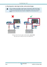
4. Pay attention to the correct orientation. The SBP is designed to allow current to flow from IN (battery) to OUT (load) terminals

only. Reverse currents from OUT to IN terminals are strictly forbidden and will damage the device. If you wish to use the SBP
as a disconnection for a charge source, you must orient the unit in the system so that the current is flowing in the intended
direction, IN to OUT.

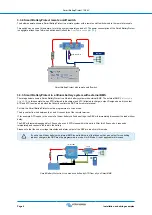
5. The short circuit protection of the SBP will be activated if you try to directly connect loads with capacitors, for example

inverters or inverter/chargers, on their DC inputs. For that use case, please use the SBP to control the remote on/off control
on the inverter, instead of disconnecting the higher power DC line. 

See also the warning on the next page

.

6. Use a 1,5mm2 wire (included) for the GND connection, which should be connected directly to the battery negative terminal (or

the chassis of a vehicle). No other equipment should be connected to this wire.

7. The pin assignment of the connectors are printed either on the front or on the side of the housing.

8. The SBP automatically detects the system voltage once only during initial power up. The selected voltage (12 or 24 V) is

stored, and further automatic detection is disabled. See "d" in the programming table for how to reset it when re-using the
SBP in a different installation or use Bluetooth.

9. Do not connect the load output until the SBP has been fully programmed.

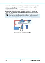
10. A remote on/off switch can be connected between Remote H and Remote L. Alternatively, terminal H can be switched high (to

battery positive), or terminal L can be switched low (to battery negative).

11. A buzzer, LED or relay can be connected between the alarm output terminal and the battery positive. Maximum load on the

alarm output: 50mA (short circuit proof).

Smart BatteryProtect 12/24V

Page 3

Installation and wiring examples

Summary of Contents for SBP-100

Page 1: ...Smart BatteryProtect 12 24V 12 24V 65A 12 24V 100A 12 24V 220A rev 00 08 2022 ENGLISH...

Page 2: ...m system with external BMS and load disconnect output 7 3 3 5 Two Smart BatteryProtects for load and charger control 8 3 3 6 Smart BatteryProtect Alarm output wiring 8 4 Operation and programming 9 4...

Page 3: ...ared to the BatteryProtect the Smart BatteryProtect can be conveniently programmed via Bluetooth and our VictronConnect app or the PROG pin to GND pin method All necessary parameters can be set in thi...

Page 4: ...ooth on This is important in case of Li ion batteries especially after low cell voltage shutdown Over voltage protection To prevent damage to sensitive loads due to over voltage The load is disconnect...

Page 5: ...otection of the SBP will be activated if you try to directly connect loads with capacitors for example inverters or inverter chargers on their DC inputs For that use case please use the SBP to control...

Page 6: ...erter charger via a SBP you must use the SBP to control the inverter or inverter charger via its remote port See example below Note that the image shown below is an example for all BatteryProtect mode...

Page 7: ...the load after 90 seconds automatically DC loads Smart BatteryProtect in a simple system with wire loop between L and H input factory default The same example below This time the switch is wired betw...

Page 8: ...ly controls the SBP via its remote terminal For this the Smart BatteryProtect must be programmed to Li ion mode The dry contact is wired between the L and H connectors of the remote terminal If for ex...

Page 9: ...gh when there is an actual low cell voltage and the SBP will disconnect the load and remains off for 30 seconds even if it receives a restart signal H becomes high again within this period After this...

Page 10: ...of the SBPs always follow the current flow from IN to OUT The positive terminal of the charger goes to the IN input of the SBP DC loads SBP 65 charge SBP 65 load Two Smart BatteryProtects take contro...

Page 11: ...SBP will disconnect the load after 90 seconds and the relay will disengage In case of over voltage the load will be disconnected immediately and the alarm output will remain inactive Overvoltage trip...

Page 12: ...t to set the restart voltage 9 Click on the 3 dots in the top right corner and then on Product info 10 In the Product info menu the PIN code can be changed a custom name can be set and Bluetooth can b...

Page 13: ...0V 3 11 25V 22 5V 13 25V 26 5V 4 11 5V 23 0V 13 8V 27 6V 5 10 5V 21 0V 12 8V 25 6V 6 11 5V 23 0V 12 8V 25 6V 7 11 8V 23 6V 12 8V 25 6V 8 12 0V 24 0V 13 0V 26 0V 9 10 0V 20 0V 13 2V 26 4V User defined...

Page 14: ...f switch to the positive supply of the BMS for this purpose Similarly if a system shutdown occurred due to low cell voltage the SBP will remain disengaged for 30 seconds even if it receives a re engag...

Page 15: ...nce in a residential installation This equipment generates uses and can radiate radio frequency energy and if not installed and used in accordance with the instructions may cause harmful interference...

Page 16: ...oad on alarm output 50mA short circuit proof Load disconnect delay 90 seconds immidiate if triggered by a BMS Load reconnect delay 30 seconds Default thresholds Disengage 10 5 V or 21 V Engage 12 V or...

Page 17: ...t draw does not exceed the SBP current rating 2 Check for loose high resistance connections and ensure that appropriate gauge wiring is used in the installation 3 Do not install the SBP unit in a loca...

Page 18: ...ween BMS and SBP Remote terminal 4 Check BMS for proper operation E8 Reverse current Reverse current protection is activated in the event that reverse current flow is detected CAUTION The SBP is desig...

Reviews: