


23
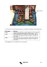
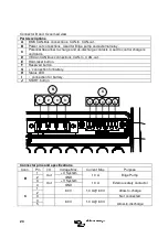
Connector B and C zoomed view
Connector pins and specifications
Conn.
Pin
I/O
Voltage Max.
Current Max.
Purpose
B
1
Out
+ V System
10 A
Bilge Pump
2
GND
3
Out
+ V System
10 A
External safety contactor
4
GND
C
1
60 V
1,0 A @ 60 V
Allow-to-charge
2
3
Not connected
4
60 V
1,0 A @ 60 V
Allow-to-discharge
5
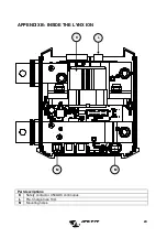
Part descriptions
A
BMS CAN-Bus connections. CAN-In, CAN-out.
B
Power out connections. Used for Bilge pump and external relay.
C
Potential free allow-to-charge and ok-discharge contacts. Used to control chargers
and loads.
D
VE.Can CAN-Bus connections. CAN-In, CAN-out.
E
Hard-reset button.
F
Reserved button.
G
‘+’ connection for battery.
H
Status LED.
I
‘-’ connection for battery.
J
START-button.
4
3
2
1
B
C
1
2
3
4
5
Summary of Contents for Lynx Ion
Page 1: ...Manual EN Lynx Ion 24V 180Ah Lithium Ion Batteries ...
Page 2: ......
Page 17: ...15 3 Start VEConfigure3 and configure the Li ion BMS Support assistant as follows ...
Page 23: ...21 APPENDIX A OVERVIEW LYNX ION Bottom view B A D E F C ...
Page 24: ...22 Front view I G H J ...
Page 28: ......


