Victor E Lock ER-55 Manual Download Page 12


12 


Step11   


Engage tailpiece 

through dead 

bolt hub. 

Correct position for 

the wire harness   

Wrong position for the wire 

harness (that will stop the 

movement of tailpiece) 

Tailpiece 

Summary of Contents for ER-55

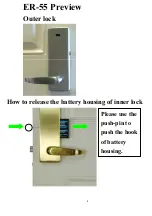
Page 1: ...1 ER 55 Preview Outer lock How to release the battery housing of inner lock Please use the push pin to push the hook of battery housing...

Page 2: ...2 ER 55 Installation Step1...

Page 3: ...3 Step2 Adjust the dead bolt Adjust the latch bolt by pushing hole Lift pin and pull the body to the right 2 3 8 2 3 4 60mm 70mm 2 3 8 2 3 4...

Page 4: ...4 Step3 Install latch bolt and dead bolt making certain both latch bolt and dead bolt hub are center to center...

Page 5: ...matically To throw the deadbolt on storeroom function enter your code and then lift the lever handle Passage Entrance Function unlike the storeroom function the door will remain unlocked after each op...

Page 6: ...6 Step5 Set the handing cam to the correct position To match your door swing R or L From outside the door hinges are on the left that is left door swing and so on R L Right door swing Left door swing...

Page 7: ...7 Step6 Thread wire harness below dead bolt chaise bypass the posts...

Page 8: ...8 Step7 Place the outer lock body to engage with the spindle in alignment the cam clutch smoothly engages with the spindle align both inside and outside housings to ensure proper installation...

Page 9: ...9 Step8 Install interior mechanism sandwich plate Sandwich plate...

Page 10: ...10 Step9 Tailpiece Direction of tailpiece vertical RIGHT HAND horizontal LEFT HAND for door swing Right door swing Left door swing...

Page 11: ...11 Step10 Engage interior mechanism through Spindle hub hole...

Page 12: ...12 Step11 Engage tailpiece through dead bolt hub Correct position for the wire harness Wrong position for the wire harness that will stop the movement of tailpiece Tailpiece X...

Page 13: ...other 4 round head screws Make certain sandwich plate screws are tight this will prevent shifting of both outside and inside plates Flat head screws must be tightened otherwise it will interfere the...

Page 14: ...14 Step13 Connect with wire harness In assembly make certain wire harness is located under the inside housing...

Page 15: ...15 Step14 Engage spindle onto coil spring and hub of inside mechanism Lever Handle Shaft Coil Spring...

Page 16: ...16 Step15 Tighten with 4 Round head screws Shorter than other 2 round head screws...

Page 17: ...17 Step16 Attach inside escutcheon...

Page 18: ...18 Step17 Tighten with two 2mm screws on both sides...

Page 19: ...19 Step18 Attach nylon washer and lever handle on inside and outside escutcheon...

Page 20: ...20 Step19 Tighten the lever handle screws with Allen wrench...

Page 21: ...0 Troubleshooting Handing Cam Reversed Right door swing Correct positions Incorrect positions Insert battery housing with batteries into the inner lock make certain batteries are in the correct direct...

Page 22: ...lock can be opened from outside without pressing the key fob Tail piece Reversed Right door swing Correct positions Incorrect positions The lock can not be opened or locked from inside or outside V x...

Page 23: ...orrect positions Incorrect positions The door swing will be the left swing Please make sure of that the two flat screws are firmly tight to the two holes on the top of interior mechanism plate otherwi...

Page 24: ...for spindle hub hole of latch The lever handles can not be pressed down or lifted up Correct positions for spindle hub hole of latch Incorrect direction of spindle The lock can not be opened or locke...

Page 25: ...d Bolt Confirm door cannot be opened from outside WHEN LOCKING DOOR LIFT LEVER HANDLE up till stop position If Lever Handle is lifted partially dead bolt may not be extended to its full potential Egre...

Page 26: ...26 Lock Door from Inner Lock Lift up lever handle to lock door Press down lever handle to unlock door...

Page 27: ...se emergency key Push the key into key hole and hold it firmly and then rotate down to unlock door Cam Lock Please disconnect the battery pack for 30 seconds whenever you use the emergency cam lock an...

Page 28: ...ator Green Light Access Code Accepted Orange Light Low Battery Passage Entrance or storeroom function at your choice included in this lock 4 AA batteries not included Burglar alarm is included in this...

Page 29: ...second until green light starts blinking and point remote control toward infrared window and press until green is sold If red light glows teaching is not successful Remote control code deletion proce...

Page 30: ...30 Burglar Alarm System Burglar alarm will immediately sound when emergency cam lock is illegally picked How to stop the sounds of Burglar Alarm System Release batteries for 30 seconds...

Reviews: