background image

12

6.

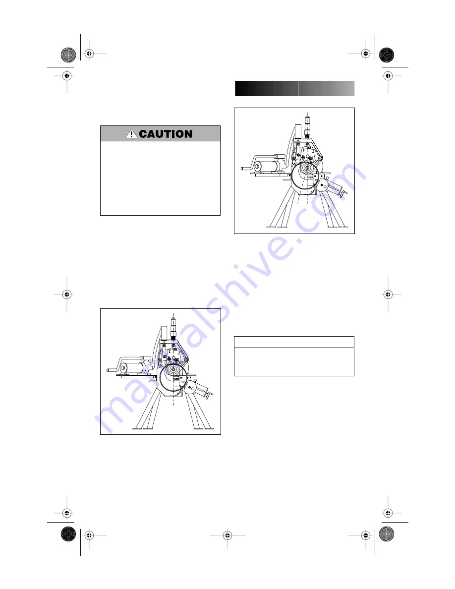
Advance stabilizer roller inward with hand-

wheel to the position indicated in Figure 3
below, then tighten locking handle.

7.

Complete the 

Pre-Operation Adjust-

ments

 and groove the pipe (see Grooving

Operation pages 14 - 16.) Observe the stabilizer
roller while grooving. It should remain in con-
tact with the pipe most of the time and the
pipe should rotate smoothly without swaying
from side to side. If not, advance stabilizer
roller further inward. Retest and make further
adjustments as necessary. Remember, do not
adjust stabilizer too far inward as it will skew
the pipe to the left and possibly result in exces-
sive pipe end flaring.

“CORRECT”

Figure 3

Do not adjust stabilizer to push pipe to the left and off
center from the rolls (see Figure 4 at right). Doing so
will cause increased pipe end flare and shorten roller
life.

• Assembly of couplings on pipe exceeding Maximum

Allowable Flare, Column 8 in the Roll Groove
Specifications charts, pages 29 - 32, may prevent
closure of couplings pad-to-pad, allowing possible
pipe separation and result in property damage.

• Also, joint leakage may result due to excessive

gasket distortion/damage.

VE270FSD

“INCORRECT”

Figure 4

GROOVE DIAMETER STOP 
ADJUSTMENT

The groove diameter stop must be adjusted for
each pipe size or change in wall thickness.
Groove diameter, identified as the “C” dimen-
sion for each pipe size, is listed under Roll
Groove Specifications, pages 29 - 32. For your
convenience, a “C” Diameter Chart for Steel
Pipe is also on the tool.

To achieve proper diameter:

1.

Determine the diameter and thickness of

the pipe to be grooved. (See the Dimensions
Charts on page 33.)

2.

Locate the proper diameter and thickness

on the pipe size indicator on the depth stop. It
is rotatable for easy viewing.

NOTICE

To perform the following adjustments, use several
short scrap sections of pipe (but not shorter than what
is recommended in Table 1, page 8) of the proper
material, diameter and thickness to be grooved.

TM-VE270FSD.2469 Rev.B  Page 12  Sunday, October 28, 2001  4:10 PM

Summary of Contents for VE270FSD

Page 1: ...ting or servicing the VE270FSD tool read this Manual and all warning labels on the tool Always wear safety glasses and foot protection If you need additional copies of the manual or have any questions...

Page 2: ...NOTICE The use of the word NOTICE signifies special instructions which are important but not related to hazards INDEX Hazard Identification 2 Operator Safety Instructions 3 General 3 Tool Setup 3 Ope...

Page 3: ...e parts for any obstructions Be sure that guards and tool parts are properly installed and adjusted 2 Prevent accidental startings 3 Operate with foot switch only The VE270FSD must be operated with a...

Page 4: ...upon tool rating amps and cord length feet Use of a cord size gauge thinner than required will cause a significant voltage drop at the gear motor while the tool is operating The voltage drop may caus...

Page 5: ...g Instructions and all warning labels on this tool Always wear safety glasses and foot protection If you have any questions about the safe operation of this tool contact Victaulic Tool Company P O Box...

Page 6: ...other materials see Tool Rating and Roll Selection charts on pages 27 and 28 Grooving rolls for other specifications sizes and other materials must be purchased separately TOOL SETUP 1 Remove all com...

Page 7: ...ion tips 1 Pipe ends should be cut squarely in accor dance with Column 2 note on appropriate Roll Groove Specification chart pages 29 32 2 Internal or external weld bead or seams must be ground flush...

Page 8: ...10 10 20 80 203 2 914 4 250 254 0 508 0 3 8 36 12 12 18 90 203 2 914 4 300 304 8 457 2 4 8 36 100 203 2 914 4 NOTICE Pipe nipples shorter than those shown in Table 1 are available from Victaulic Examp...

Page 9: ...of couplings pad to pad allowing possible pipe separation and result in property damage Also joint leakage may result due to excessive gasket distortion damage NOTICE For additional information about...

Page 10: ...Preparation on page 7 Grooving rolls can crush or cut fingers and hands Loading and unloading pipe will place your hands close to the rollers Never groove pipe shorter than what is recommended in Tabl...

Page 11: ...tool without retracting stabilizer Unplug power cord until instructed otherwise Accidental start up of tool may result in serious personal injury VE270FSD 1 Make sure proper roll set is on the tool fo...

Page 12: ...in the Roll Groove Specifications charts pages 29 32 may prevent closure of couplings pad to pad allowing possible pipe separation and result in property damage Also joint leakage may result due to ex...

Page 13: ...the tool carefully check the groove diameter C dimension as charted on pages 29 32 under Roll Groove Specifications The C dimension is best checked with a Pi tape It may also be checked with a vernier...

Page 14: ...Before operating tool review all safety precautions on page 3 Failure to do so may result in serious personal injury To reduce the risk of electric shock check the electrical source for proper ground...

Page 15: ...ing until the depth stop comes into full firm contact with top of tool body Continue pipe rotation for one 1 to three 3 revolutions to assure groove completion 11 Release safety foot switch and withdr...

Page 16: ...ter Stop Adjustment Groove diameter should be checked periodically and adjusted as necessary to assure grooves are within specification Always unplug power cord before changing rolls Accidental start...

Page 17: ...e to fragmentation Always wear eye protection Always use supplied aluminum wedge for roll removal Always use soft faced hammers with aluminum wedge Never strike rolls directly for any reason UPPER ROL...

Page 18: ...om the main shaft The arbor shaft features three 3 20 UNC tapped holes so that jack bolts can be used to push out the arbor shaft ROLL INSTALLATION PROCEDURE See Rating and Roll Selection Chart on pag...

Page 19: ...ion LOWER ROLLS 1 1 SIZES 1 Clean the bore of the main shaft and the roll assembly parts with a soft cloth 2 Lightly lubricate the roll assembly parts with the proper lubricant Dow Corning G n mechani...

Page 20: ...n of the stud clockwise ROLL INSTALLATION PROCEDURE LOWER ROLL 2 AND LARGER SIZES 1 Place lower roll onto arbor shaft Reposition guards if necessary to make assembly easier Make sure lower roll fits f...

Page 21: ...vided as shown with a No 2EP Lithium base grease NOTICE Remember that preventative maintenance during operation will pay for itself in repair and operating savings Before performing any repair or main...

Page 22: ...AULIC SYSTEMS The level of hydraulic fluid in the pump must be checked semi annually or if pumping feels spongy FILLING AND CHECKING 1 Open pump release valve fully by turning counterclockwise 2 Remov...

Page 23: ...side of the tool PARTS ORDERING INFORMATION When ordering parts the following information is necessary for Victaulic to process the order and send the correct part s Request RP 270FSD Parts Manual fo...

Page 24: ...th pipe ends Contact Victaulic for details VAPS 224 Also available is Victaulic Model 224 It has fea tures similar to Model 112 It is suitable for pipe sizes from 2 24 Consult Victaulic for details ST...

Page 25: ...y removal hole s Press out the remains of broken key s and install new Woodruff 605 and or 608 key s Install lower roll see Roll Changing Open release valve to free pipe close release valve and contin...

Page 26: ...urthest point where it still stabilizes pipe effectively Pipe sways or vibrates from side to side Incorrect stabilizer adjustment Optional stabilizer was not purchased installed and used Move stabiliz...

Page 27: ...3 0 237 0 237 0 337 Lower Roll R904272L06 Upper Roll R9A2272U06 Lower Roll RZ04272L06 Upper Roll RZA4272U06 114 3 2 1 6 0 6 0 6 0 2 1 6 0 6 0 8 6 4 0 095 0 237 0 237 0 237 0 095 0 237 127 0 2 4 6 0 6...

Page 28: ...0 156 0 180 323 9 4 0 4 6 All wall thicknesses are nominal minimum and maximum Types 304 304L and 316 316L The following O D sized pipe also may be roll grooved 3 O D 4 O D 5 O D 5 O D 6 O D 6 O D 6...

Page 29: ...0 101 6 101 6 1 02 0 79 15 88 8 74 97 38 0 51 2 11 2 11 104 1 4 O D 4 250 0 043 0 031 0 625 0 344 4 084 0 020 0 083 0 083 4 35 108 0 108 0 1 04 0 79 15 88 8 74 103 73 0 51 2 11 2 11 110 5 4 4 500 0 04...

Page 30: ...e must be of uniform depth for the entire pipe circumference Groove must be maintained within the C diameter tolerance listed COLUMN 6 Groove depth For reference only Groove must conform to the groove...

Page 31: ...ing size COLUMN 2 Outside diameter The outside diameter of roll grooved tubing shall not vary more than the tolerance listed The max imum allowable tolerance from square cut ends is 0 030 0 8 mm for 2...

Page 32: ...ence only Groove must conform to the groove diameter C listed COLUMN 7 Minimum allowable wall thickness This is the minimum wall thickness which may be grooved COLUMN 8 Maximum allowable pipe end flar...

Page 33: ...4 6 6 6 6 9 5 6 6 625 0 109 0 134 0 280 0 280 0 432 168 3 168 3 2 8 3 4 7 1 7 1 11 0 8 8 625 0 109 0 148 0 250 0 277 0 322 0 322 0 500 219 1 219 1 2 8 3 8 6 4 7 0 8 2 8 2 12 7 10 10 750 0 134 0 165 0...

Page 34: ...e right to change product specifications designs and standard equipment without notice and without obligation Registered Trademark of Victaulic Copyright 2000 Victaulic Printed in U S A R TM VE270FSD...

Reviews: