VD520 Series Inverter User Manual Parameter Description
- 121 -
F5 Input Terminal Group
VD520 series inverter with six multi-function digital input terminals (including HDI1 can be used as a
high speed pulse input terminal), two analog input terminals.
F5-00
Terminal Command
Mode
0: Two-line mode 1
1: Two-line mode 2
2: Three-line mode 1
3: Three-line mode 2
4: Alternate control
5: Back and forth control
0
◎
This parameter defines five different modes of controlling the operation of the inverter via the external
terminals
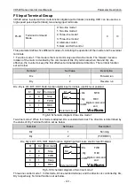
1: Two-line mode 1: This mode is the most commonly used two-line mode. The forward / reverse
rotation of the motor is decided by the commands of Dix, DIy terminals; when Dix and DIy are
effective, the inverter to keep the first effective terminal determined direction. The terminal function
set as below:
Terminal
Set Value
Description
Dix
1
Forward run
DIy
2
Reverse run
DIx, DIy is DI1~DI5, HDI1 Multi-function digital input terminals, electric level enabled.
External circuit
K1
K2
0
0
1
0
0
1
1
1
Command
Stop
FWD
REV
Keep
DIx
DIy
COM
FWD
REV
K1
K2
Digital command
end
VicRuns
Fig 6-9 Schematic diagram of two line mode 1
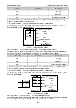
Two-line mode 2: When this mode is adopted, DIx is enabled terminal. The direction is determined by
the status of DIy. Terminal function set as below.
Terminal
Set Value
Description
DIx
1
Running
DIy
2
(FWD/REV)
DIx, DIy is DI1~DI5, HDI1 Multi-function digital input terminals, electric level Enabled.
Extemal circuit
K1
K2
0
0
1
0
0
1
1
1
Command
Stop
FWD
Keep
REV
DIx
DIy
COM
FWD
REV
K1
K2
Digital command
end
VicRuns
Fig 6-10 Schematic diagram of two line mode 2
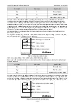
Three-line control mode 1: In this mode, Dln is enabled terminal, and the direction is controlled by DIx,
DIy respectively. Terminal function set as below.

