VD520 Series Inverter User Manual Parameter Description
- 97 -
Chapter 6 Parameter Description
F0 Basic Function
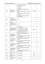
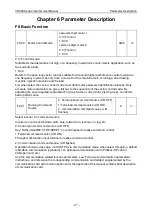
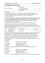
F0-00
Motor Control Mode
Led unit’s digit: motor 1
0: V/F control
1: SVC
Led ten’s digit: motor 2
0: V/F control
1: SVC
0x00
◎
0: V/F control mode:
Suitable for load demand is not high, or a frequency inverter drive multi-motors application, such as
fan and pump load.
1: SVC
Refers to the open loop vector control, suitable for the usual higher performance control occasions,
one frequency inverter can only drive a motor. Such as machine tools, centrifuge, wire drawing
machine, injection machine and the load.
Tip: when select the vector control mode must done motor parameter identification process. Only
accurate motor parameter can give a full pay to the superiority of the vector control mode. By
adjusting the speed regulator parameter F3 group function code (motor 2 is A3 group), can obtain
better performance.
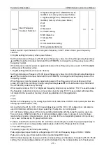
F0-01
Running Command
Source
0: Control panel command source (L/R OFF)
1: Terminal command source (L/R ON)
2: communication command source (L/R
flashes)
0
○
Select inverter run command source:
Inverter run command include: start, stop, forward run, reverse run, jog, etc.
0: Control panel command source (L/R OFF)
Key” RUN, JOG/REV, STOP/RESET” on control panel to realize command control.
1: Terminal command source (L/R ON)
Through multi-function input terminal to realize command control.
2: Communication command source (L/R flashes)
Operation command as setup via HOST PC via communication mode, when select this option, default
is Modbus communication (standard), can optional communication card (Profibus-DP card or
CANopen card, etc.).
And the communication related
function parameters, see “Fd group communication parameters”
instructions, and reference the corresponding communication card added, supplemented by the
communication card with communication card, the appendix of this manual contains brief description
of communication card.


