background image

V-CELL-HD Quick Installation Guide


2. Installation 

 
For the network camera to operate, it is necessary to connect a network cable for data transmission 
and power connection from customer-supplied power supply. 
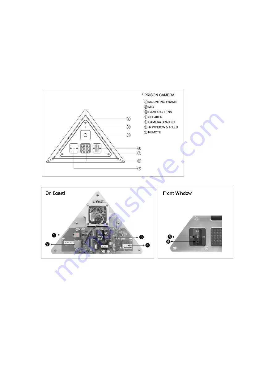
 

2.1 Exploded View 


Parts and Description 


  Main Power 24VAC/12VDC (

(+) pole /

(-) pole) 

 RJ45(PoE) Port 

 Micro-SD Card Slot 

  Alarm & Audio In/Out Port 

 Status LED 

    Upon boot-up, green and red are both on for a short time and then only green will be on.   

If red is lit, this indicates a failure (no picture); if flashing green and no red, 
this indicates a good picture is displaying. 

  Service Monitor Port   


3

Summary of Contents for V-CELL-HD

Page 1: ...y as described in the documentation This system has not been designed to be used in life critical situations and must not be used for this purpose Vicon Industries Inc Tel 631 952 2288 Fax 631 951 2288 Toll Free 800 645 9116 24 Hour Technical Support 800 34 VICON 800 348 4266 UK 44 0 1489 566300 Document Number 8009 8247 30 01 Product specifications subject to change without notice Issued 114 Copy...

Page 2: ...ing is designed to fit into a corner once installed the base plate should be permanently sealed to the wall so that the housing is ligature proof The housing consists of a two part stainless steel assembly a fixed base plate and a removable front plate that allows ease of installation and servicing The front plate is secured with security screws and has two polycarbonate windows to protect the cam...

Page 3: ...ied power supply 2 1 Exploded View Parts and Description Main Power 24VAC 12VDC pole pole RJ45 PoE Port Micro SD Card Slot Alarm Audio In Out Port Status LED Upon boot up green and red are both on for a short time and then only green will be on If red is lit this indicates a failure no picture if flashing green and no red this indicates a good picture is displaying Service Monitor Port 3 ...

Page 4: ... on mounting surface Fig 1 2 Drill holes for mounting base and a minimum 3 4 in hole for routing wines Fig 1 3 Mount camera mounting frame using appropriate hardware for mounting surface Fig 2 4 Route wires through hole in wall and out through base plate Fig 2 5 Terminate wires to camera board 6 Mount front plate to base plate Fig 2 4 ...

Page 5: ...ert cable clamp into access hole route cables through clamp and mount cover using appropriate hardware 4 Use camera mounting frame to mark its mounting holes drill holes and mount using appropriate hardware 5 Terminate wires to camera board Feed the excess wire back through cable clamp and tighten clamp 6 Mount front plate to camera mounting frame Note Installation of the rear cover is required fo...

Page 6: ...he Alarm Out and GND connectors Connecting the Power Connect the power of 12 VDC or 24 VAC for the network camera Connect the positive pole to the position and the negative pole to the position for the DC power Use Certified Listed Class 2 power source Connecting Service Monitor Port The Service Monitor output port is located on the board of the camera and is used for easy OSD setup ID IP assignme...

Page 7: ...work does not have a DHCP server the network camera will use 192 168 1 100 as the default IP address If DHCP is enabled and the product cannot be accessed run the Smart Manager utility on the CD to search and allocate an IP address to your product or reset the product to the factory default settings and then perform the installation again 1 Connect the network camera device to the network and powe...

Page 8: ...net Explorer set your browser to allow ActiveX controls Note Some screens may appear different i e color scheme depending on the firmware version but the functionality is the same or similar 3 1 Access from a browser 1 Start a browser Internet Explorer 2 Enter the IP address or host name of the Network Camera in the Location Address field of your browser 3 A starting page displays Click Live View ...

Page 9: ...played when the network camera is accessed for the setup at the first time Enter your admin name and password set by the administrator Note The default administrator username is ADMIN and password is 1234 If the password is lost the network camera must be reset to the factory default settings See section 3 5 Resetting to the Factory Default Settings for more details To prevent network eavesdroppin...

Page 10: ... combination of protocols and methods to use depending on your viewing requirements and on the properties of the network 2 Control toolbar The live viewer toolbar is available in the web browser page only It displays the following buttons The Stop button stops the video stream being played Pressing the key again toggles the start and stop The Start button connects to the network camera or starts p...

Page 11: ...factory settings go to the Setup System Maintenance web page described in 3 5 7 System Maintenance of the User s Manual or use the Reset button SW1 on the board of the dome camera as described below Using the Reset Button Follow the instructions below to reset the network camera to the factory default settings using the Reset button 1 Switch off the network camera by disconnecting the power adapte...

Page 12: ...HD V CELL Network Camera 50303765B Vicon Industries Inc Internet Address www vicon security com ...

Reviews: